– 118 –
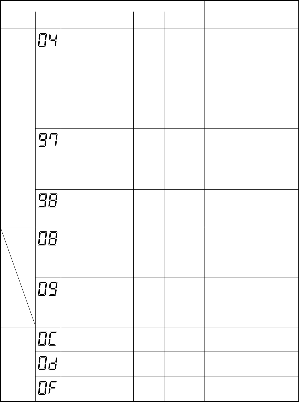
14-3. Check Code Table
Error mode detected by indoor unit (1)
Operation of diagnostic function
Block
display
[MODE]
[TIMER] lamp
5Hz flash
Check
code
Cause of operation
The serial signal is not output
from outdoor unit to indoor unit.
• Miscabling of inter-unit cables
• Defective serial sending
circuit on outdoor P.C. board
• Defective serial receiving
circuit on outdoor P.C. board
• Compressor case thermo
operation
Status of air
conditioner
Operation
continues
Condition
Displayed when
error is detected
Judgment and measures
1. Outdoor unit does not completely
operate.
• Inter-unit cable check, correction of
miscabling
• Outdoor P.C. board check, P.C. board
cables check
• Compressor case thermo check
2. In normal operation
When outdoor sending serial LED
(Green) flashes, the receiving serial
LED (Orange) also flashes. : Indoor
P.C. board (Main P.C. board) check
When the receiving serial LED
(Orange) does not flash: Outdoor P.C.
board check
[MODE] lamp
5Hz flash
*
Operation
continues
(According
to remote
controller of
indoor unit)
Operation
continues
Operation
continues
Operation
continues
Operation
continues
Operation
continues
Operation
continues
Displayed when
error is detected
Displayed when
error is detected
Displayed when
error is detected
Displayed when
error is detected
Displayed when
error is detected
Displayed when
error is detected
Displayed when
error is detected
1. Communication line check, miscabling
check
Power supply check for central
controller (Central control remote
controller, etc.) and indoor unit
2. Communication check (XY terminal)
3. Indoor P.C. board check
4. Central controller check
(Communication P.C. board)
BUS communication circuit error
* BUS communication was
interrupted over the specified
time.
1. Check central control system network
address setting. (SW02)
2. Indoor P.C. board check
3. Central controller check
(Communication P.C. board)
Network address miss-setting
• Addresses of central
controllers (Central control
remote controller, etc.) are
duplicated.
Error in 4-way valve system
• Indoor heat exchanger
temperature rise after start of
cooling operation.
• Indoor heat exchanger
temperature fall after start of
heating operation.
1. Check 4-way valve.
2. Check 2-way valve and non-return
valve.
3. Check indoor heat exchanger sensor
(TC).
4. Check indoor P.C. board (Main P.C.
board).
Error in other cycles
• Indoor heat exchanger temp
(TC) does not vary after start
of cooling/heating operation.
1. Compressor case thermo operation
2. Coming-off of detection part of indoor
heat exchanger sensor
3. Check indoor heat exchanger sensor
(TC).
4. Check indoor P.C. board (Main P.C.
board).
1. Check indoor temp sensor (TA).
2. Check indoor P.C. board (Main P.C.
board).
Coming-off, disconnection or
short of indoor temp sensor
(TA)
1. Check indoor temp sensor (TC).
2. Check indoor P.C. board (Main P.C.
board).
Coming-off, disconnection or
short of indoor temp sensor
(TC)
1. Check indoor temp sensor (TCJ).
2. Check indoor P.C. board (Main P.C.
board).
Coming-off, disconnection or
short of indoor temp sensor
(TCJ)
*
: No display in the setting at shipment


