


– 86 –
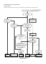
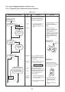
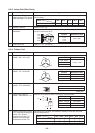
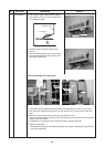
11-9-3. Indoor Unit (Other Parts)
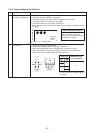
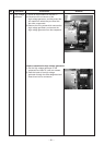
11-9-4. Outdoor Unit
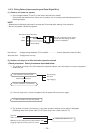
5
4
3
2
1
White
Yellow
Yellow
Yellow
Yellow
5
4
3
2
1
Red
White Blac
k
Red
White Blac
k
COM
COM
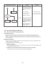
254
Y
W
BR
BL
1
R
6
O
3
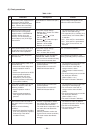
No.
1
2
3
4
Part name
Room temp. (TA) sensor
Heat exchanger (TC) sensor
Heat exchanger (TCJ) sensor
Remote controller
Louver motor
MP24Z3N
Indoor fan motor
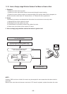
Checking procedure
Disconnect the connector and measure the resistance value with tester.
(Normal temp.)
Temperature
Sensor
TA, TC, TCJ (kΩ)
10°C 20°C 25°C 30°C 40°C
20.7 12.6 10.0 7.9 4.5
Refer to 11-5-1. (5).
Measure the resistance value of each winding coil by using the tester.
(Under normal temp. 25°C)
Position
1 to 2
1 to 3
1 to 4
1 to 5
Resistance value
250 ± 20Ω
Refer to 11-5-1. (3) and (4).
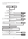
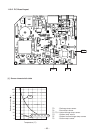
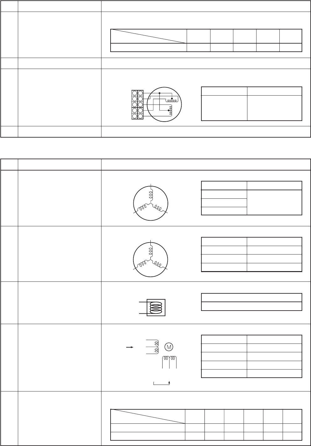
No.
1
2
3
4
5
Part name
Compressor
(Model : DA111A1F-24F)
Outdoor fan motor
(Model : ICF-140-43-4R)
4-way valve coil
(Model : STF-01AJ502E1)
Pulse motor valve coil
(Model : CAM-MD12TF-10)
Outdoor temperature sensor
(TO), discharge temperature
sensor (TD), suction
temperature sensor (TS),
outdoor heat exchanger
temperature sensor (TE)
Checking procedure
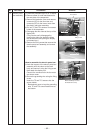
Measure the resistance value of each winding by using the tester.
Position
Red - White
White - Black
Black - Red
Resistance value
1.02 to 1.12Ω
Under 20°C
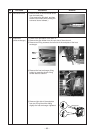
Measure the resistance value of winding by using the tester.
Position
Red - White
White - Black
Black- Red
Resistance value
20 to 22Ω
20 to 22Ω
20 to 22Ω
Under 20°C
Measure the resistance value of winding by using the tester.
Resistance value
1435 ± 144Ω
Under 20°C
Measure the resistance value of winding by using the tester.
Position
Red - White
White - Orange
Brown- Yellow
Brown- Blue
Resistance value
42 to 50kΩ
42 to 50kΩ
42 to 50kΩ
42 to 50kΩ
Under 20°C
Disconnect the connector, and measure resistance value with the tester.
(Normal temperature)
Temperature
Sensor
TD (kΩ)
TO,TS,TE (kΩ)
10°C 20°C 25°C 30°C 40°C 50°C
100 64 50 41 27 18
20.7 12.6 10.0 7.9 4.5 —