– 48 –
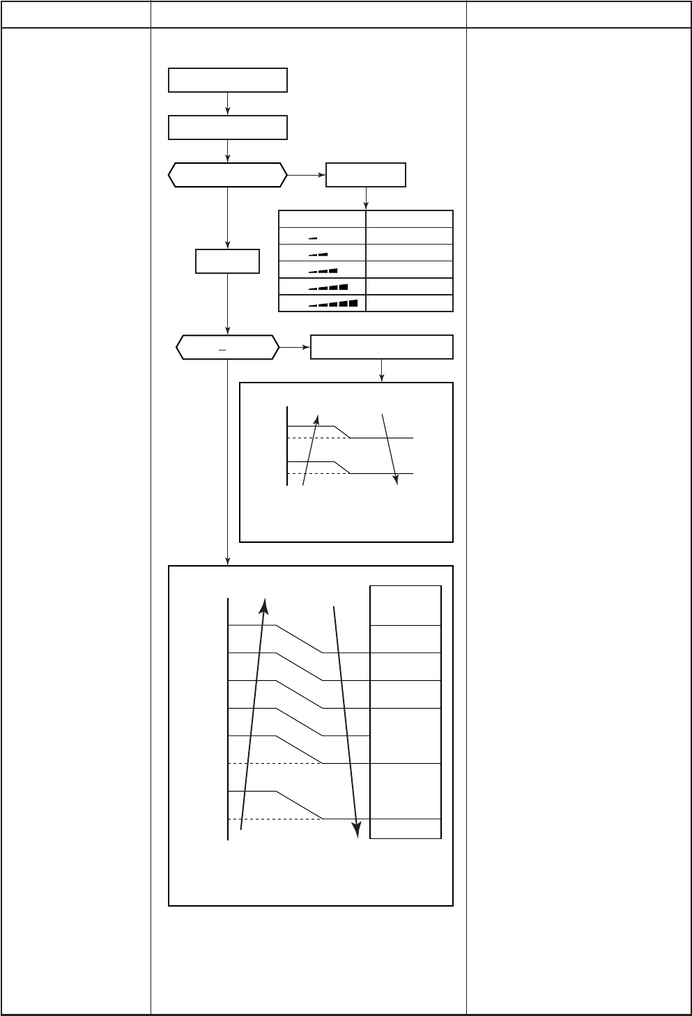
Push [8˚C] button.
Fan speed AUTO
Fan speed setup
AUTO
TC
>
42˚C
MANUAL
Min air flow rate control
Basic fan control
Indication Fan speed
W8
(L + M) / 2
WA
(M + H) / 2
WE
L
L+
M
M+
H
∗ Fan speed=
(TC – (42 + a)) / 10 × (WD – W8) + W8
a: In up operation 1, in down operation 0
∗1: Fan speed = (M + –L) × 1 ÷ 4 + L
∗2: Fan speed = (M + –L) × 2 ÷ 4 + L
∗3: Fan speed = (M + –L) × 3 ÷ 4 + L
(Calculated with linear approximation from M+ and L)
Limited to Min WD tap
No limit
Fan speed
AUTO
L (W8)
b
c
d
e
f
g
M + (WD)
H (WE)
∗1
∗2
∗3
–5.5
–5.0
–2.5
–2.0
–1.5
–1.0
–0.5
TA [˚C]
TSC
TC
52
51
42
41
∗
YES
NO
Item
20. 8°C HEAT operation
(-ND model only)
Operation flow and applicable data, etc.
<Indoor fan control>
<Compressor speed control>
Refer to 4. Capacity control.
Description
<Indoor fan control>
When 8°C HEAT operation, the
indoor fan control rises up automati-
cally.
When the indoor fan is operated
manually, it is matched with the fan
tap. However the cold draft preventive
control becomes invalid.
<Compressor speed control>
The compressor speed control is
carried out according to 4. Capacity
control.


