


– 59 –
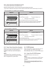
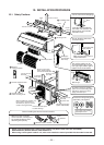
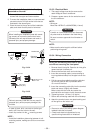
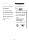
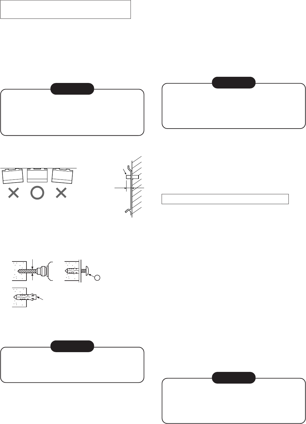
When the installation plate is directly
mounted on the wall
1. Securely fit the installation plate onto the wall by
screws with the upper and lower catches.
2. To mount the installation plate on a concrete wall
use anchor bolts. Drill the anchor bolt holes as
illustrated in the above figure.
3. Place the level at the top end of the installation
plate, and check that the plate is horizontal.
CAUTION
When installing the installation plate with mount-
ing screws, do not use the anchor bolt holes.
Otherwise the unit may fall down and result in
personal injury and property damage.
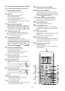
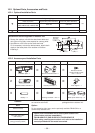
Fig. 10-3-4
Fig. 10-3-5
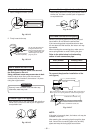
CAUTION
Failure to securely install the unit may result in
personal injury and/or property damage if the
unit falls.
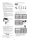
• In case of block, brick, concrete or similar type
walls, drill 5 mm dia. holes in the wall.
• Insert clip anchors for the
mounting screws.
NOTE :
• Install the installation plate using between 4 to 6
mounting screws, making sure all four corners are
secure.
Anchor bolt
Projection
15mm or less
5 mm dia. hole
Clip anchor
(local parts)
6 Mounting screw
Ø4 × 25L
10-3-3. Electrical Work
1. The supply voltage must be the same as the
rated voltage of the air conditioner.
2. Prepare a power source for the exclusive use of
the air conditioner.
NOTE :
• Wire type :
More than H07RN-F or 60245IEC66 (1.0mm²)
CAUTION
A switch or circuit breaker that can disconnect
all poles must be included in the fixed wiring.
Be sure to use an approved circuit breaker or
switch.
NOTE :
• Make sure the wire length is sufficient before
performing wiring work.
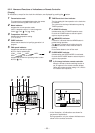
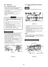
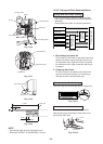
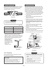
10-3-4. Wiring Connection
How to connect the connecting cable
Wiring the connecting cable can be carried
out without removing the front panel.
1. Remove the air inlet grille. Open the air inlet grille
upward and pull it toward you.
2. Remove the terminal cover and cord clamp.
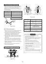
3. Insert the connecting cable (or as according to
local regulations/codes) into the pipe hole on the
wall.
4. Pull the connecting cable through the cable slot
on the rear panel so that it protrudes about
15 cm out of the front.
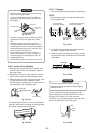
5. Insert the connecting cable fully into the terminal
block and secure it tightly with screws.
Make a loop with the earth wire under the
terminal block and secure it with the earth screw.
6. Tightening torque: 1.2 N•m (0.12 kgf•m)
7. Secure the connecting cable with the cord clamp.
8. Attach the terminal cover, rear plate bushing and
air inlet grille on the indoor unit.
CAUTION
• Be sure to refer to the wiring system diagram
labeled inside the front panel.
• Check local electrical regulations for any
specific wiring instructions or limitations.