


Getting Started Model GFC7001E Carbon Dioxide Analyzer
Teledyne Analytical Instruments 44
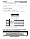
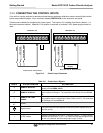
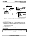
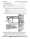
3.4.2. PNEUMATIC CONNECTIONS TO GFC 7001E/EM BASIC
CONFIGURATION
NOTE
In order to prevent dust from getting into the gas flow channels of your analyzer, it was shipped with
small plugs inserted into each of the pneumatic fittings on the back panel.
Make sure that all of these dust plugs are removed before attaching
exhaust and supply gas lines.
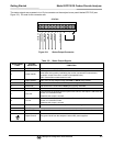
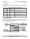
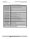
See Figure 3-2 and Table 3-2 for the location and descriptions of the various pneumatic inlets/outlets referred to
in this section.
See Section 5.6 for information regarding the pneumatic setup of GFC 7001E/EM Analyzers with various optional
calibration valve options in stalled
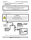
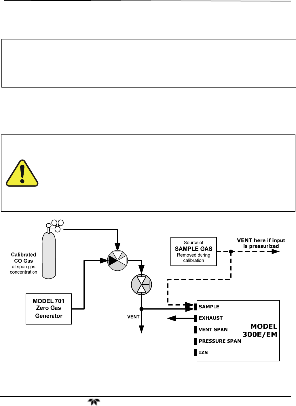
CAUTION
GENERAL SAFETY HAZARD
Sample and calibration gases should only come into contact with PTFE (Teflon), FEP,
glass, stainless steel or brass.
The exhaust from the analyzer’s internal pump MUST be vented outside the immediate
area or shelter surrounding the instrument.
It is important to conform to all safety requirements regarding exposure to CO.
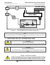
Figure 3-10: Pneumatic Connections–Basic Configuration–Using Bottled Span Gas