


Troubleshooting & Repair Model GFC7001E Carbon Dioxide Analyzer
Teledyne Analytical Instruments 290
13.5.5. RELAY BOARD
The relay board PCA (P/N 04135) can be most easily checked by observing the condition of the its status LED’s
on the relay board, as described in Section 13.1.4.3, and the associated output when toggled on and off through
signal I/O function in the diagnostic menu, see Section 13.1.3.
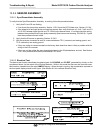
1. If the front panel display responds to key presses and D1 on the relay board is NOT flashing then either
the wiring between the Keyboard and the relay board is bad, or the relay board is bad.
2. If D1 on the relay board is flashing and the status indicator for the output in question (heater power,
valve drive, etc.) toggles properly using the signal I/O function, then the associated control device on
the relay board is bad.
Several of the control devices are in sockets and can be easily replaced.
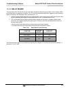
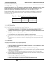
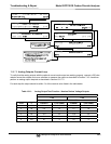
The table below lists the control device associated with a particular function:
Table 13-8: Relay Board Control Devices
FUNCTION
CONTROL
DEVICE
IN SOCKET
Wheel Heater K1 Yes
Bench Heater K2 Yes
Spare AC Control K3 Yes
IZS Valves U4 Yes
IR Source Drive U5 No
The IR source drive output can be verified by measuring the voltage at J16 with the IR source disconnected. It
should be 11.5± 0.5 VDC.