


Performance Tests
TDS 520A, 524A, 540A, & 544A Performance Verification
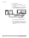
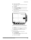
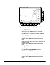
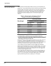
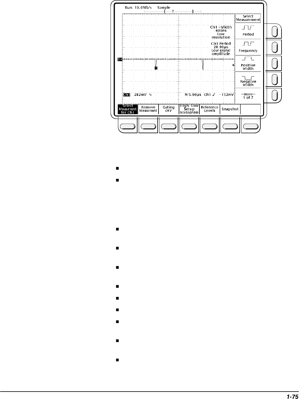
Figure 1-41: Sync Duty Cycle Test: Critically Adjusted Pulse
Press TRIGGER MENU.
Press the main-menu Type pop-up until you select Video.
If the TRIG’D LED is not on, check that the CH1 – Width and
CH1 Period measurements are adjusted correctly (see note
above). CONFIRM that the setup is correct and the oscilloscope
will trigger.
CONFIRM that the TRIG’D LED is on and the waveform is
stable.
Disconnect the signal source from CH1, wait a few seconds, then
reconnect the signal.
CONFIRM that the TRIG’D LED is on and the waveform is
stable.
Press Sync Polarity.
Press Pos Sync.
Push the pulse generator COMPLEMENT button out.
CONFIRM that the TRIG’D LED is on and the waveform is
stable.
Disconnect the signal source from CH1, wait a few seconds, then
reconnect the signal.
CONFIRM that the TRIG’D LED is on and the waveform is
stable.