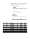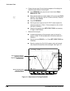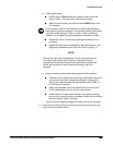
Performance Tests
Performance Verification Procedures
Check Analog Bandwidth
Equipment Required:
One high-frequency leveled sine wave generator and
its leveling head (Item 11), plus two10X attenuators (Item 1).
Prerequisites:
See page 1-15.
Procedure:
1.
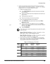
Install the test hookup and preset the instrument controls:
a.
Initialize the oscilloscope:
Press save/recall SETUP.
Press the main-menu button Recall Factory Setup.
Press the side-menu button OK Confirm Factory Init.
b.
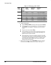
Modify the default settings:
Set the horizontal SCALE to 50 ns.
Now press SHIFT, then ACQUIRE MENU.
Press the main-menu button Mode; then press the side-menu
button Average 16.
Press TRIGGER MENU.
Press the main-menu button Coupling; then press the side-
menu button Noise Rej.
Press Measure. Now press the main-menu button High–Low
Setup; then press the side-menu button Min–Max.
c.
Hook up the test-signal source:
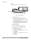
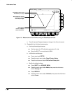
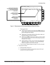
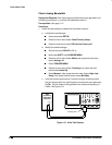
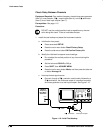
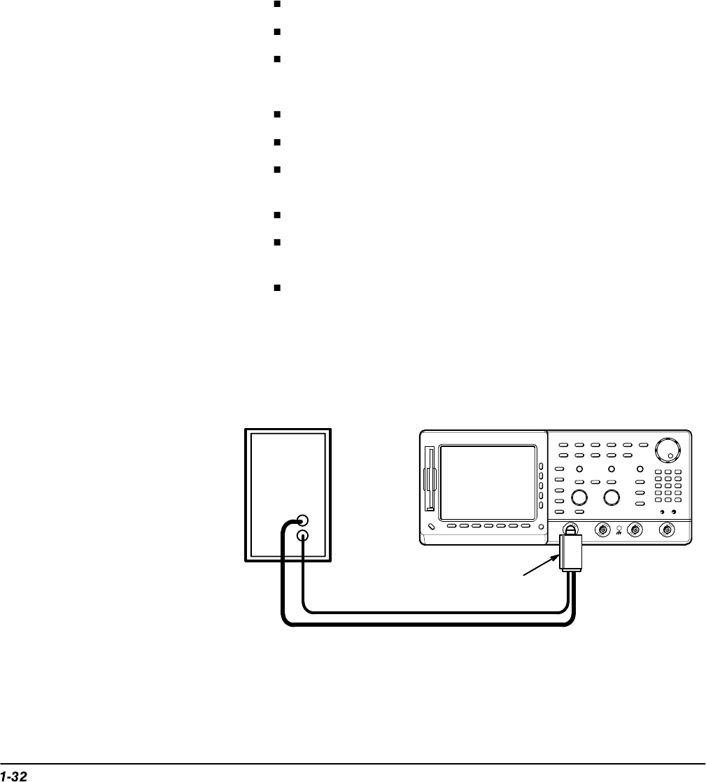
Connect, through its leveling head,
the sine wave output of a high-frequency leveled sine wave generator
to CH 1. Set the output of the generator to a reference frequency of
6 MHz. See Figure 1-8.
High
Frequency
Sine Wave
Generator
Leveling Head
Output
Figure 1-8: Initial Test Hookup


