


Performance Tests
TDS 520A, 524A, 540A, & 544A Performance Verification
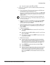
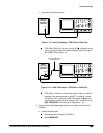
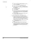
Press the side-menu button Upper Limit; then use the general
purpose knob to slowly
decrease
the the Upper Limit readout
until triggering is lost.
CHECK that the Upper Limit readout is within 1 s to 3 s,
inclusive.
4.
Disconnect the hookup:
Disconnect the cable from the generator output
at the input connector of CH 1.
Check Accuracy, Trigger-level or Threshold, DC Coupled
Equipment Required:
One DC calibration generator (Item 8), one BNC T
connector (Item 6), and two precision, 50 , coaxial cables (Item 4).
Prerequisites:
The oscilloscope must meet the prerequisites listed on
page 1-15.
Procedure:
1.
Install the test hookup and preset the instrument controls:
a.
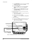
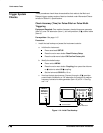
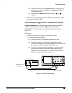
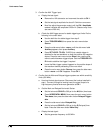
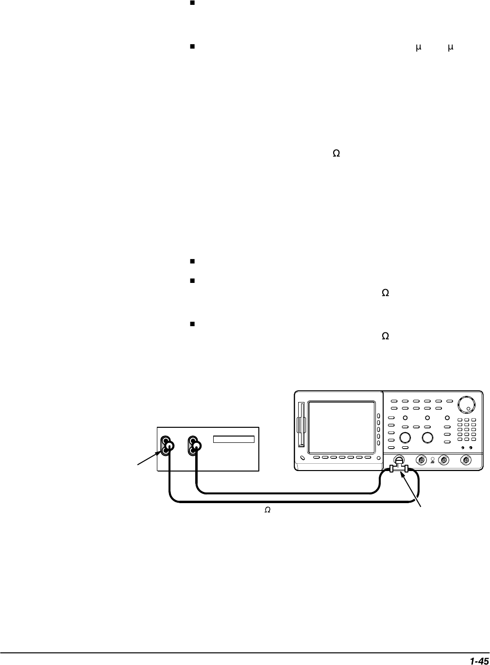
Hook up the test-signal source:
Set the output of a DC calibration generator to 0 volts.
Connect the output of a DC calibration generator through a
dual-banana connector followed by a 50 precision coaxial cable
to one side of a BNC T connector. See Figure 1-16.
Connect the Sense output of the generator, through a second
dual-banana connector followed by a 50 precision coaxial
cable, to other side of the BNC T connector. Now connect the
BNC T connector to CH 1. See Figure 1-16.
HI
LO
Output Sense
DC Calibrator
50
Coaxial Cables
Dual Banana to
BNC Adapter
BNC T Connector
Figure 1-16: Initial Test Hookup