


Performance Tests
Performance Verification Procedures
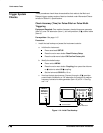
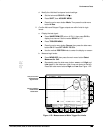
Press the main-menu button High-Low Setup; then press the
side-menu button Min-Max.
Press the main-menu button Select Measrmnt for
Ch1
.
Press the side-menu button –more– until Amplitude appears in
the side menu (its icon is shown at the left). Press the side-menu
button Amplitude.
Press SET LEVEL TO 50%.
Press CLEAR MENU.
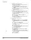
Set the test signal amplitude for about three divisions on screen.
Now fine adjust the generator output until the CH 1 Amplitude
readout indicates the amplitude is 350 mV. (Readout may fluctu-
ate around 350 mV.)
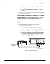
Disconnect the 50 precision coaxial cable at CH 1 and recon-
nect it to CH 1 through a 10X attenuator.
b.
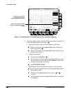
Check for Main trigger system for stable triggering at limits:
Read the following definition: A stable trigger is one that is con-
sistent; that is, one that results in a uniform, regular display
triggered on the selected slope (positive or negative). This display
should
not
have its trigger point switching between opposite
slopes, nor should it “roll” across the screen. At horizontal scale
settings of 2 ms/division and faster, TRIG’D will remain constantly
lit. It will flash for slower settings.
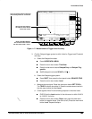
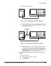
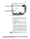
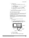
Press TRIGGER MENU; then press the main-menu button
Slope.
Press SET LEVEL TO 50%. CHECK that a stable trigger is
obtained for the test waveform on both the positive and negative
slopes. (Use the side menu to switch between trigger slopes; use
the TRIGGER LEVEL knob to stabilize the trigger if required.)
See Figure 1-20.