


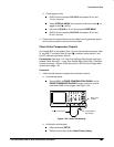

Performance Tests
Performance Verification Procedures
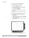
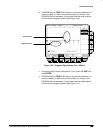
Adjust the output of DC calibration generator until it precisely
overlaps the top (upper) level of the stored probe compensation
signal. (This value will be near 500 mV.)
Record the setting of the DC generator.
Adjust the output of DC calibration generator until it precisely
overlaps the base (lower) level of the stored probe compensation
signal. (This value will be near zero volts.)
Record the setting of the DC generator.
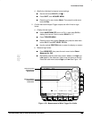
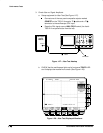
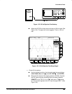
d. Press CLEAR MENU to remove the menus from the display. See
Figure 1-26.
Figure 1-26: Measurement of Probe Compensator Amplitude
e.
Check against limits:
Subtract the value just obtained (base level) from that obtained
previously (top level).
CHECK that the difference obtained is within 495 mV to 505 mV,
inclusive.
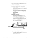
4.
Disconnect the hookup:
Disconnect the cable from CH 1.