


Performance Tests
TDS 520A, 524A, 540A, & 544A Performance Verification
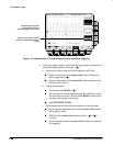
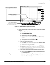
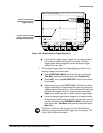
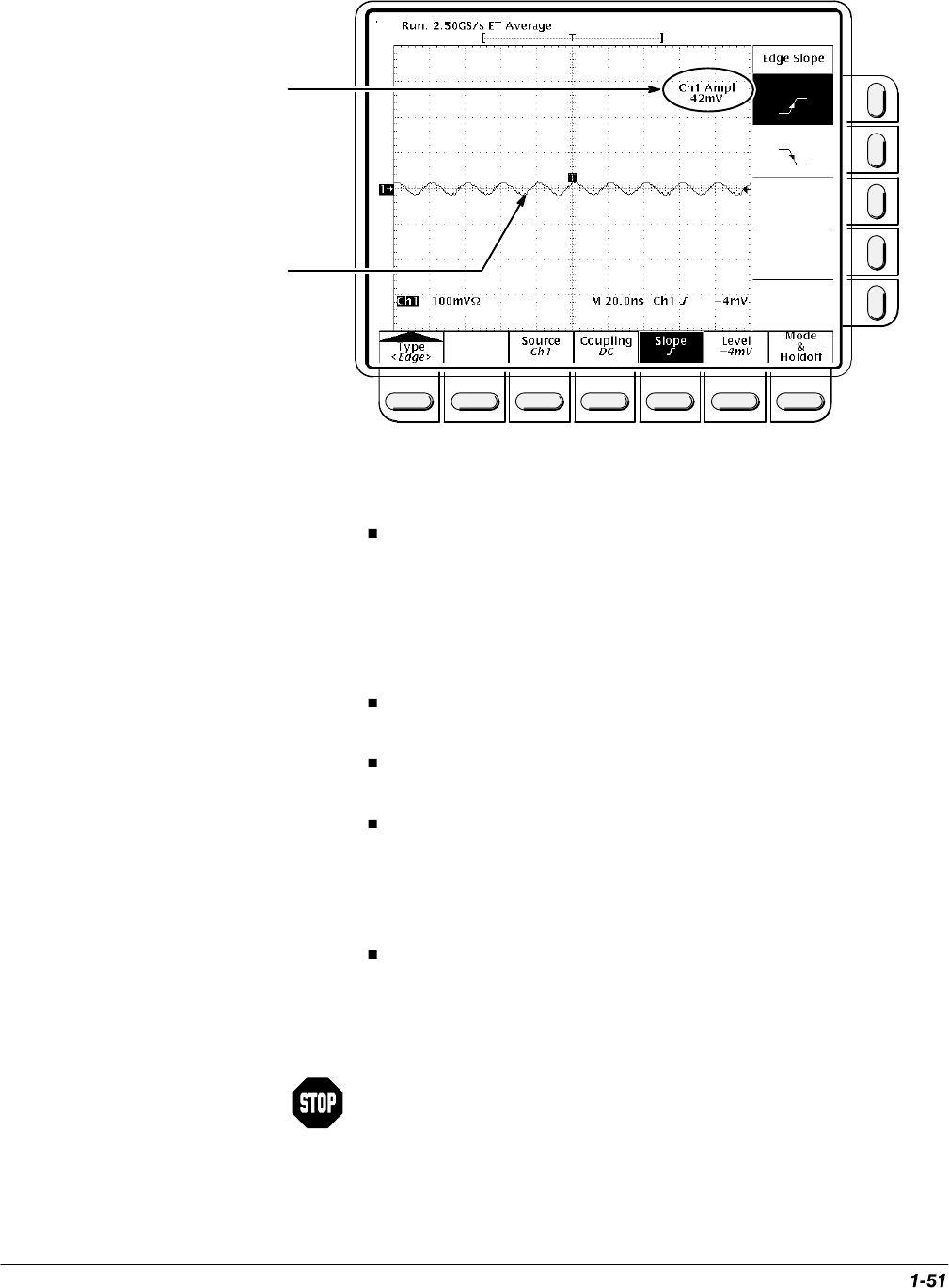
First, set a signal with an
amplitude at the minimum
trigger sensitivity.
Second, check for a stable
trigger at both the positive
and negative slope settings.
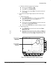
Figure 1-20: Measurement of Trigger Sensitivity
Leave the Main trigger system triggered on the positive slope of
the waveform before continuing to the next step. (The Main
trigger system must be triggered to check the delayed trigger
system in the next step.)
c.
Check delayed trigger system for stable triggering at limits:
Do the
following subparts in the order listed.
Press HORIZONTAL MENU; then press the main-menu button
Time Base. Now press the side-menu button Delayed Only.
Press SHIFT; then press DELAYED TRIG. Press the main-menu
button Level.
Press the
side
-
menu
button SET TO 50%. CHECK that a stable
trigger is obtained for the test waveform for both the positive and
negative slopes of the waveform. (Use the General Purpose knob
to stabilize the trigger if required.) Press the main-menu button
Slope; then use the side menu to switch between trigger slopes.
Leave the delayed trigger system triggered on the positive slope
of the waveform before continuing to the next step. Also, return to
the main time base: Press HORIZONTAL MENU; then press the
main-menu button Time Base. Now press the side-menu button
Main Only.
TDS 520A or 524A only: Skip to step 4 since the TDS 520A and
524A are not equipped with an AUX Trigger input. If testing the TDS
540A or 544A, continue with step 3.