


NOTE: DIAGRAMS & ILLUSTRATIONS ARE NOT TO SCALE.
35
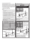
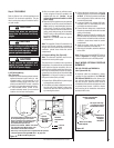
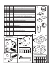
SIT Millivolt Gas Valve
Pressure
Regulator
Remove
These
Components
Figure 58
Step 1. Turn off the gas supply to the appli-
ance.
Remove the control compartment door
(see Figure 47 on Page 27).
Remove the front glass doorframe
from the appliance (see Figure 53 on
Page 30).
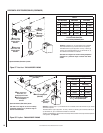
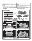
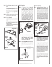
Step 2. Carefully remove the logs. Exercise
care so as not to break the logs.
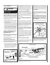
Step 3. Refer to Figure 57.
.25
.25 a. Above the burner, remove the two
baffl e securing screws. Remove the
baffl e.
.25
.25 b. Remove the two screws securing
the trapezoidal plate to the burner.
Remove the plate.
.25
.25 c. Remove the burner assembly with
attached venturi tube.
Burner Assembly
Gas Valve
Assembly
Orifice
Figure 57
Millivolt Appliances
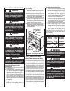
Step 4. SIT Systems - Refer to Figure 58
on Page 35 and the instructions
provided with the kit. Using a Torx
T20 or a fl at screwdrive, remove and
discard the three pressure regula-
tor mounting screws. Remove the
pressure regulator, spring, poppet,
diaphragm and bushing. Discard all
removed components. Ensure the
rubber gasket installed on the back of
the replacement pressure regulator
is properly positioned and install the
new pressure regulator using the new
screws supplied with the kit. Tighten
screws to 25 In. lb. torque.
Step 5. Attach manometer to the manifold
side pressure test fi tting and verify
manifold pressure reads 3.5 inches
water column (0.87 kPa) for natural
gas, and 10.0 inches water column
(2.49 kPa) for propane gas.
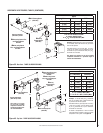
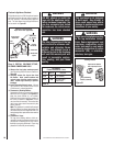
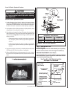
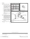
Step 6. Refer to Figure 59 and remove the pilot
hood assembly to access the hexed
pilot orifi ce. Remove and replace the
orifi ce with the one provided with the
kit.
Pilot for SIT Millivolt
Gas Valve
Figure 59
Pilot
Orifi ce
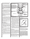
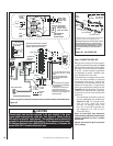
Electronic Appliances
Step 7. Honeywell Electronic Valves - See
Figure 60 and the instructions pro-
vided with the kit. Remove the slotted
cap screw, o-ring, pressure-regulating
adjusting screw and spring. Retain all
parts for possible later use. Install new
components from the kit. Black cap
and red spring for propane gas units.
Silver cap and stainless steel spring for
natural gas units. Before installing the
cap, attach manometer to the manifold
side pressure test fi tting and adjust
screw until pressure reads 3.5 inches
water column (0.87 kPa) for natural
gas, and 10.0 inches water column
(2.49 kPa) for propane gas.
Figure 60
Spring
Adjusting
Screw
Slotted
Cap
P
S
I
OFF
I
ON
CONTROL
IG
N
IT
E
Manifold
Pressure
Test Port
Inlet Pressure Test Port
See Figure 62 and replace the pilot
orifi ce as follows: Remove the igniter
assembly retainer clip, and carefully
remove the igniter assembly.
Exercise extreme care to prevent
damage to or breakage of the igniter
assembly. Remove the screw secur-
ing the pilot assembly to its mounting
bracket. Back off the fl are nut at the
end of the pilot gas line to free the pilot
assembly from the gas line. Remove
the pilot orifi ce and replace it with the
one provided with the conversion kit.
Reinstall the pilot assembly by revers-
ing the steps detailed here.
When reinstalling the igniter assembly,
use extreme care to prevent damage
and breakage. Do not apply any le-
verage to the igniter assembly while
restoring the retainer clip to its original
position.