


NOTE: DIAGRAMS & ILLUSTRATIONS ARE NOT TO SCALE.
26
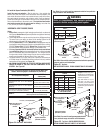
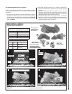
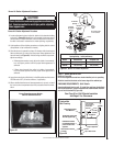
Step 6. CONNECTING GAS LINE
Make gas line connections. All codes require a
shut-off valve mounted in the supply line. Figure
46 illustrates two methods for connecting the
gas supply. The fl ex-line method is acceptable
in the U.S., however, Canadian requirements
vary depending on locality. Installation must
be in compliance with local codes.
These appliances are equipped with a gas fl ex
line for use (where permitted) in connecting
the appliance to the gas line. A gas fl ex line
is provided to aid in attaching the direct vent
appliance to the gas supply. The gas fl ex line
can only be used where local codes permit. See
Figure 46 for fl ex line description. The fl ex line
is rated for both natural gas and propane gas.
A manual shut off valve is also provided with
the fl ex line.
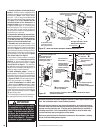
The incoming gas line should be piped into
the valve compartment and connected (see
Figures 47 & 48). The millivolt control
valve has a 3/8" (10 mm) NPT thread
inlet port. The electronic control valve
has a 1/2" (13 mm) NPT thread inlet port
and is fi tted with a 1/2" x 3/8" (13 mm x
10 mm) NPT fi tting.
Secure all joints tightly using appropriate
tools and sealing compounds (ensure propane
resistant compounds are used in propane
applications).
Optional: Seal around the gas line to prevent
cold air leakage.
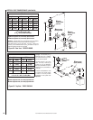
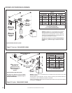
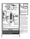
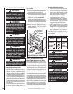
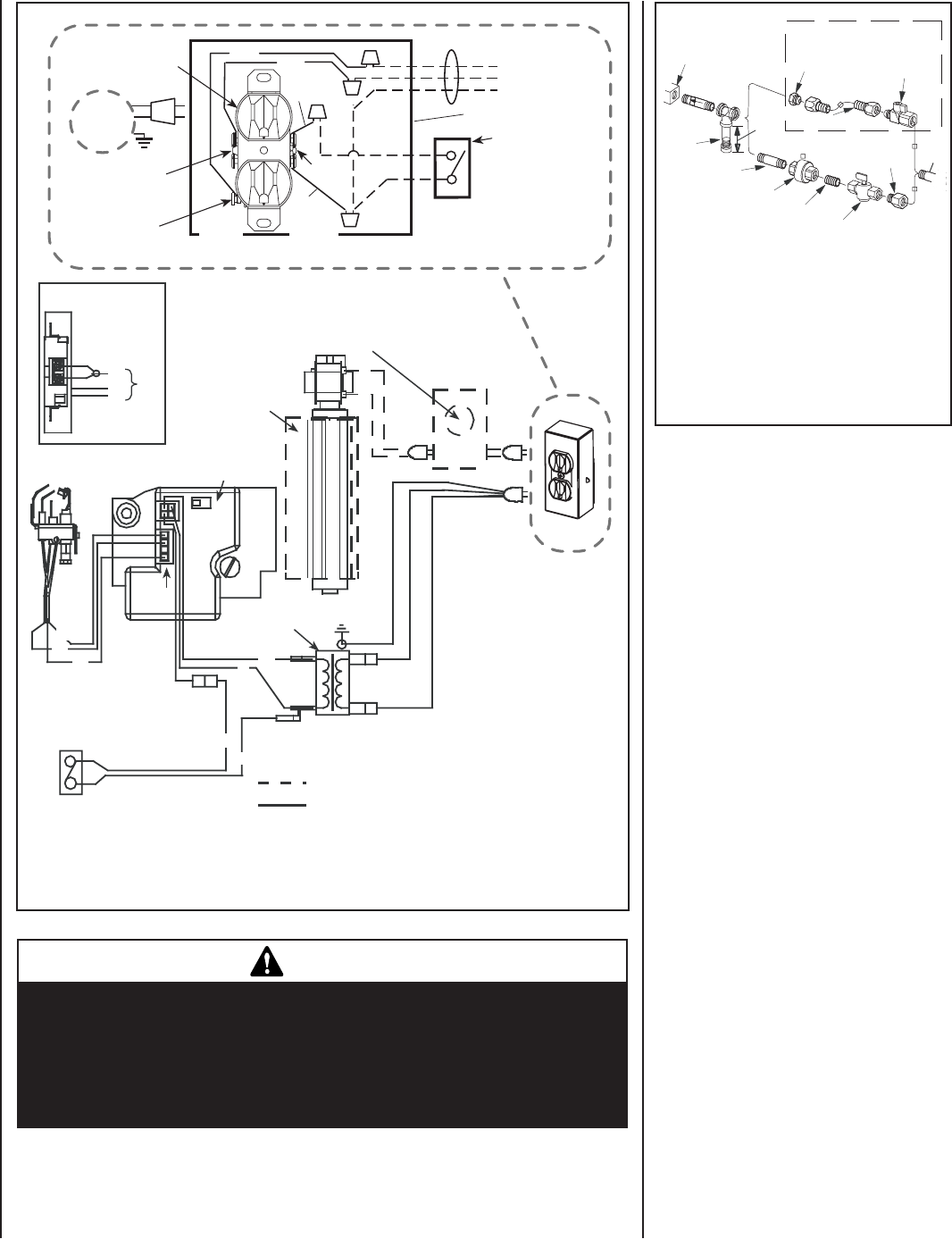
Electronic Wiring Diagram (Honeywell) Showing Blower Wiring for Optional FBK-100, FBK-200 & FBK-250 Kits
Schematic Representation Only
Relay Module C/W FBK-250 only. Plug blower
into J-Box receptacle for FBK-100 or FBK-200
application. See View A for J-Box wiring.
Optional Blower
*OFF/ON Switch
(Integral with
Gas Valve)
Honeywell
Electronic
Gas
Valve
120 VAC
Primary
Secondary
Optional Control Switch
Junction Box
Pilot Burner
Assembly
BL
BL
Field Wired
Factory
Wired
BK = BLACK BL = BLUE
R = RED W = WHITE
G = GREEN
BK
W
BK
BK
BL
R
GROUND
24 V
Transformer
View A
J-Box Wiring when
using unit mounted
relay module.
BK
W
G
CAV 021
Igniter
Connector
* Leave the OFF/ON switch, which is
integral with the gas valve, in the ON
position.
**Optional Control Switches: Wall
Switch, Wall Thermostat or Remote
Control Receiver.
Notes:
1. If any of the original wire as supplied
must be replaced, use Type AWM 105°C
- 18 gage wire ONLY.
2. 120 VAC, 60 Hz - Less than 3 Amps.
Caution: label all wires prior to
disconnection when servicing controls.
Wiring errors can cause improper and
dangerous operation.
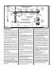
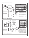
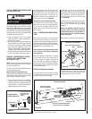
Junction Box
Tab Intact
Tab
Broken
Plug blower
into this
receptacle
n
e
e
r
G
-
dn
u
o
r
G
* Wall-mounted
ON/ OFF Blower
Switch or Variable
Speed Control Switch.
Blower
Ground
e
ti
h
W
-
lar
t
u
e
N
120 VAC - Black
Green
Ground
Screw
White
Green
Neutral
Side of
Receptacle
Hot
Side of
Receptacle
Red
Black
J-BOX WIRING FOR
WALL SWITCH
BLOWER CONTROL
Figure 45
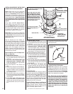
Note:The gas supply line must be installed in accor-
dance with building codes by a qualifi ed installer
approved and/or licensed as requed by the locality.
In the Commonwealth of Massachusetts, installa-
tion must be performed by a licensed plumber or
gas fi tter.
Gas
Valve
3/8" NPT x
Flare Fitting
3/8" Flex Tubing
3/8" Nipple
3/8" Union
3/8" Close Nipple
3/8" Shut-off Valve
1/2" x 3/8"
Reducer
Gas
Stub
1/2" x 3/8" Flare
Shut-off Valve
Gas Flex Line Connector
*Sediment
Trap
3"
Min
*A Sediment Trap is recommended to prevent moisture
and debris in gas line from damaging the valve.
Figure 46 - GAS CONNECTION
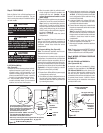
CAUTION
Ground supply lead must be connected to the wire attached to the green
ground screw located on the outlet box. See Figure 47. Failure to do so
will result in a potential safety hazard. The appliance must be electrically
grounded in accordance with local codes or, in the absence of local codes,
the National Electrical Code, ANSI/NFPA 70-latest edition. (In Canada, the
current CSA C22-1 Canadian Electrical Code).