


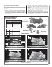
NOTE: DIAGRAMS & ILLUSTRATIONS ARE NOT TO SCALE.
25
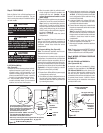
CAUTION
Ensure that wires are positioned
away from hot surfaces and sharp
edges.
CAUTION
Do not connect the optional wall
switch for burner operation to a
120 Volt AC power supply.
CAUTION
Label all wires prior to disconnection
when servicing controls. Wiring
errors can cause improper and dan-
gerous appliance operation.
Step 4. FIELD WIRING
Refer to Section A for millivolt appliances and
Section B for electronic appliances. The gas
valve is set in place and pre-wired at the factory
on both models.
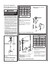
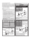
A. SIT Millivolt Wiring
(See Figure 43) –
1. Select any of the following optional controls:
appliance-mounted (rocker switch) or wall-
mounted switch, wall thermostat, or the
standard or deluxe remote control kits. If ap-
pliance-mounted ON/OFF control is selected
mount it in the gas valve mounting bracket.
2. If wall-mounted ON/OFF control or ther-
mostat is selected mount it in a convenient
location on a wall near the fi replace.
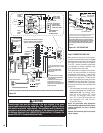
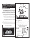
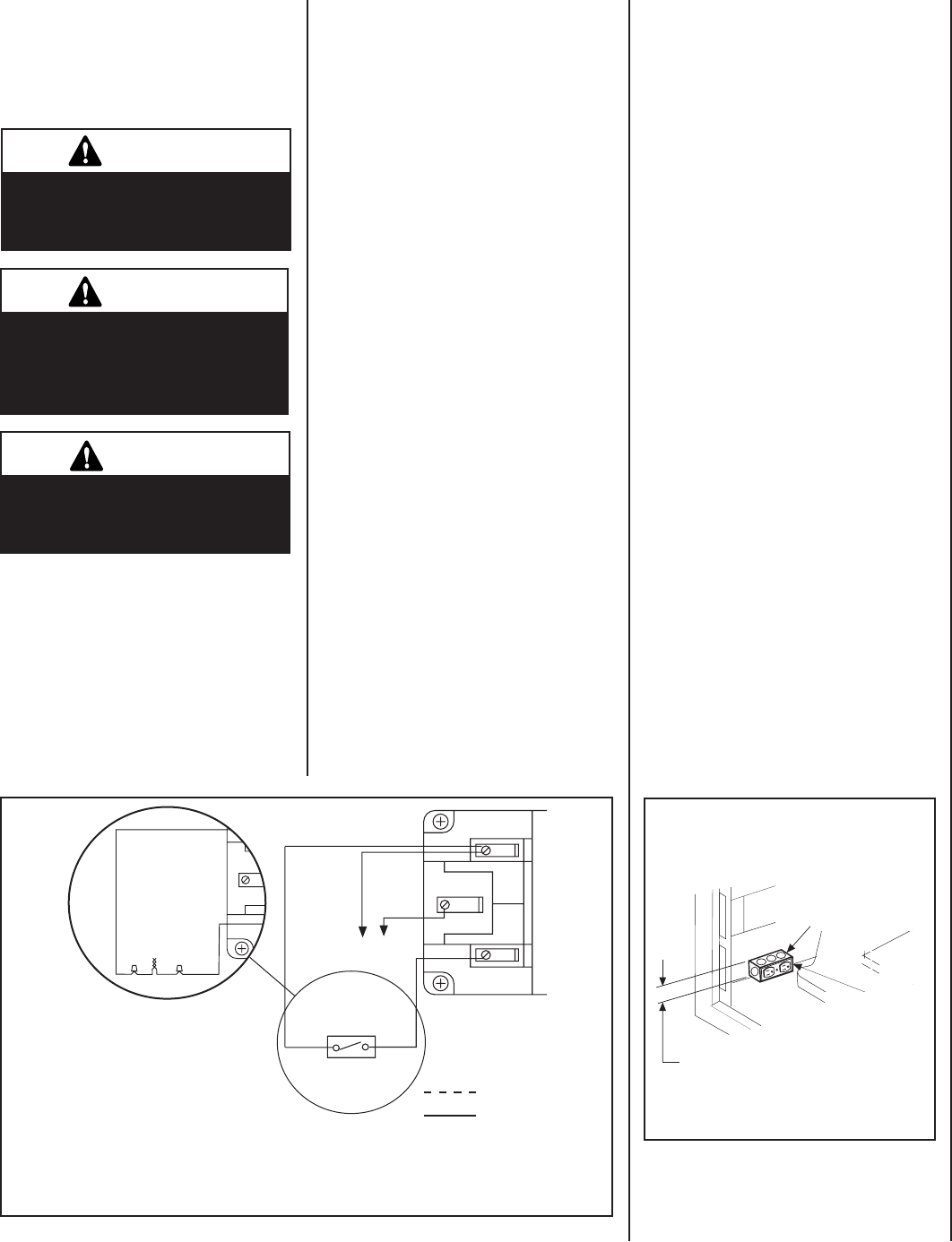
Figure 43-
SIT Millivolt Wiring Diagram
3. Connect the power supply wires (including
the ground supply wire) as shown in Figures
44 & 45. (If the fi eld-provided J-box/outlet
box is being used, all of the outlet box wiring
must be fi eld-provided).
4. Locate and install a low voltage (24V) wall-
mounted switch or thermostat (both fi eld-
provided)in the desired location.
5. Connect the low voltage wire, located inside
the control compartment, to the wall-mounted
switch or thermostat.
Note: The supplied 15 feet of 2 conductor wire
has one end of each conductor connected to
the gas valve circuit and the other end of each
conductor placed loose inside the control
compartment.
6. Insert the control circuit plug into the un-
switched receptacle of the outlet box.
7. After wiring is complete, mount the outlet box
to the J-Box.
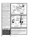
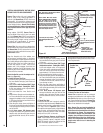
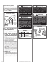
Note: The gas valve-mounted ON/OFF switch is
shown in Figure 48. It is integral with the gas
valve and should be set to the ON position.
Step 5. WIRING - OPTIONAL FORCED AIR
BLOWER KIT
FBK-100, FBK-200 and FBK250 Kits
(See Figures 44 & 45) -
An electrical outlet box (receptacle) is factory
-provided for the installation of the FBK-100,
FBK-200 and FBK-250 forced air blower kits.
(An optional fi eld-provided outletbox/J-Box
may also be used. Electrical power must be
connected to either of these receptacles in order
to operate these blowers. Install the blower
kits according to the installation instructions
provided with the kits.
3. Wire the control within the millivolt control
circuit using the 15 feet of 2 conductor wire
supplied with the unit . Caution: do not
connect the optional wall switch to a 120V
power supply.
4. Alternatively, the appliance may be operated
without the use of the controls indicated in
Step 1, solely by manipulating the gas valve
control knob. In order to use this method,
twist the free ends of the two conductor wire
(which would otherwise go to the standard
ON/OFF switch or Optional Switch) together
as shown in Figure 43.
Note: Wire is located inside the control
compartment
Note: The supplied 15 feet of 2 conductor wire
has one end of each conductor connected to
the gas valve circuit and the other end of each
conductor placed loose inside the control
compartment.
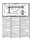
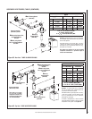
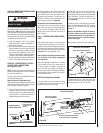
B. Electronic Wiring (See Figure 45) –
Note: The electronic appliance must be con-
nected to the main power supply.
The junction box is located on the right side of
the appliance. It contains a factory installed and
wired outlet box (duplex receptacle). Also, an
optional fi eld-provided junction box with recep-
tacle may be installed at the front of the control
compartment on either side of the cabinet. See
Figure 44. It will be held in place by a conduit
fi tting and locknut (fi eld-provided).
1. Route a 3-wire 120Vac 60Hz 1ph power supply
to the appliance junction box.
2. If the factory-provided outlet/junction box at
the right rear of the fi replace is being used,
remove the outlet box from the junction box
by removing two screws.
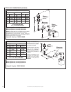
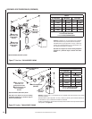
Figure 44
Field Wired
Factory
Wired
TH
TP
TH
TP
* Optional
Control Switch
Thermopile
Schematic
Representation
Only
PT
*
* Twist wires together to operate unit solely
by manipulating the gas valve control
knob; or connect wires to optional control
switch (wall switch, remote control or
wall thermostat to operate unit.
* Optional Kits Installed - ON/OFF wall switch,
unit mounted burner ON/OFF switch, wall
thermostat or remote control receiver.
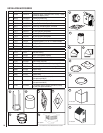
• Note: If any of the original wire as supplied must be replaced,
it must be replaced with Type AWM 105 C - 18 gage wire.
See Figure 13 on Page
11 for Optional Electrical
Inlet Knockout Location
*Field-Provided
Junction Box
and Duplex
Receptacle
*Narrow (2-1/8" Wide)
J-Box Required
Optional J-Box/Outlet Box
(Left Side Shown)