


NOTE: DIAGRAMS & ILLUSTRATIONS ARE NOT TO SCALE.
13
Figure 17a
Figure 16
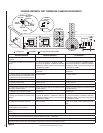
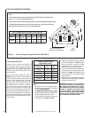
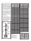
Select Venting System -
Horizontal or Vertical
With the appliance secured in framing, de-
termine vent routing and identify the exterior
termination location. The following sections
describe vertical (roof) and horizontal (exterior
wall) vent applications. Refer to the section
relating to your installation. A list of approved
venting components is shown on Pages 32
to 34.
Figure 15
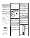
Step 3. INSTALL THE VENT SYSTEM
General Information
These instructions should be used as a guide-
line and do not supersede local codes in any
way. Install vent according to local codes,
these instructions, the current National Fuel
Gas Code (ANSI-Z223.1) in the USA or the
current standards of CAN/CGA-B149.1 and
-B149.2 in Canada.
Use only approved venting components. See
Approved Vent Components on Page 2.
These fi replaces must be vented directly
to the outside.
The vent system may not service multiple
appliances, and must never be connected to a
fl ue serving a solid fuel burning appliance. The
vent pipe is tested to be run inside an enclosing
wall (such as a chase). There is no requirement
for inspection openings in the enclosing wall at
any of the joints in the vent pipe.
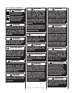
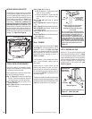
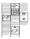
Preparing the Appliance Vent Collar
Each of the unit's two vent collars are sealed
with a cover plate and a seal cap. The cover
plate and seal cap must be removed from the
cent collar being used. Refer to Figure 15 for
top vent usage and Figure 16 for rear, and
the following steps to prepare the appropriate
collar for use.
From the vent collar being used, remove the
screw securing the vent seal cap. Twist the cap
counterclockwise to disengage it from the vent
collar. Remove and discard the seal cap.
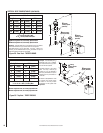
When the top vent is being used, remove the
lintel cover plate by pushing it back towards
the rear of the fi replace by its front fl ange. It
can then be removed by pulling it forward.
Loosen the two screws in the keyhole slots of
the vent cover plate and remove the remaining
two vent cover plate securing screws. Remove
and discard the vent cover plate. Reinstall and
securely tighten all four cover plate screws.
Reinstall the lintel cover plate.
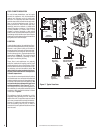
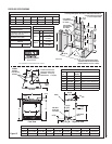
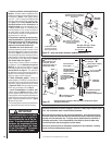
When the rear vent is being used, from inside
the fi rebox, remove the two screws securing the
baffl e to the rear wall of the fi rebox, then remove
the baffl e. Loosen the two screws in the keyhole
slots of the cover plate and remove the remaining
two cover plate securing screws. Remove and
discard the cover plate. Reinstall and securely
tighten all four cover plate screws. Re-secure
the baffl e to the rear wall of the fi rebox.
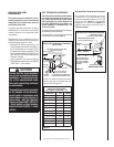
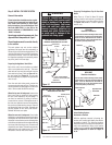
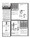
Preparing The Appliance Top Or Rear Vent
Outlet
When There Is 3 Feet Or More Of Vertical
Venting, install a vent restrictor (provided) in
the appliance top or rear fl ue outlet as shown
in Figures 17a & 17b. It is held in place by
friction, only.
VENT SEAL CAP
FIREBOX TOP
CABINET TOP
SECURING SCREWS
VENT
COVER PLATE
TOP VENT
TOP VENT SEAL CAP & COVER PLATE
REMOVAL WHEN USING THE TOP VENT
VENT COVER PLATE
SECURING SCREW
CROSS SECTION
(INSIDE UNIT)
(OUTSIDE UNIT)
LINTEL
LINTEL
COVER PLATE
PUSH TO BEGIN REMOVAL
PROCESS OF LINTEL COVER PLATE
VENT SEAL CAP
SECURING SCREWS
CROSS SECTION
BAFFLE
SECURING
SCREWS
BAFFLE
REAR VENT
COVER PLATE
SECURING SCREWS
REAR VENT SEAL CAP & COVER PLATE REMOVAL
WHEN USING THE REAR VENT
CABINET BACK
(INSIDE UNIT)
(OUTSIDE UNIT)
TOP VENT
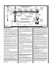
Restrictor Installation
If 3 ft. or more of vertical venting is used, install
a vent restrictor in the top vent of the fi replace
outlet. It can be installed from the inside or
outside of the unit, in the inner fi replace collar.
It is held in place by friction only.
Appliance Top
Vent Outlet
Restrictor
Inner
Fireplace
Collar
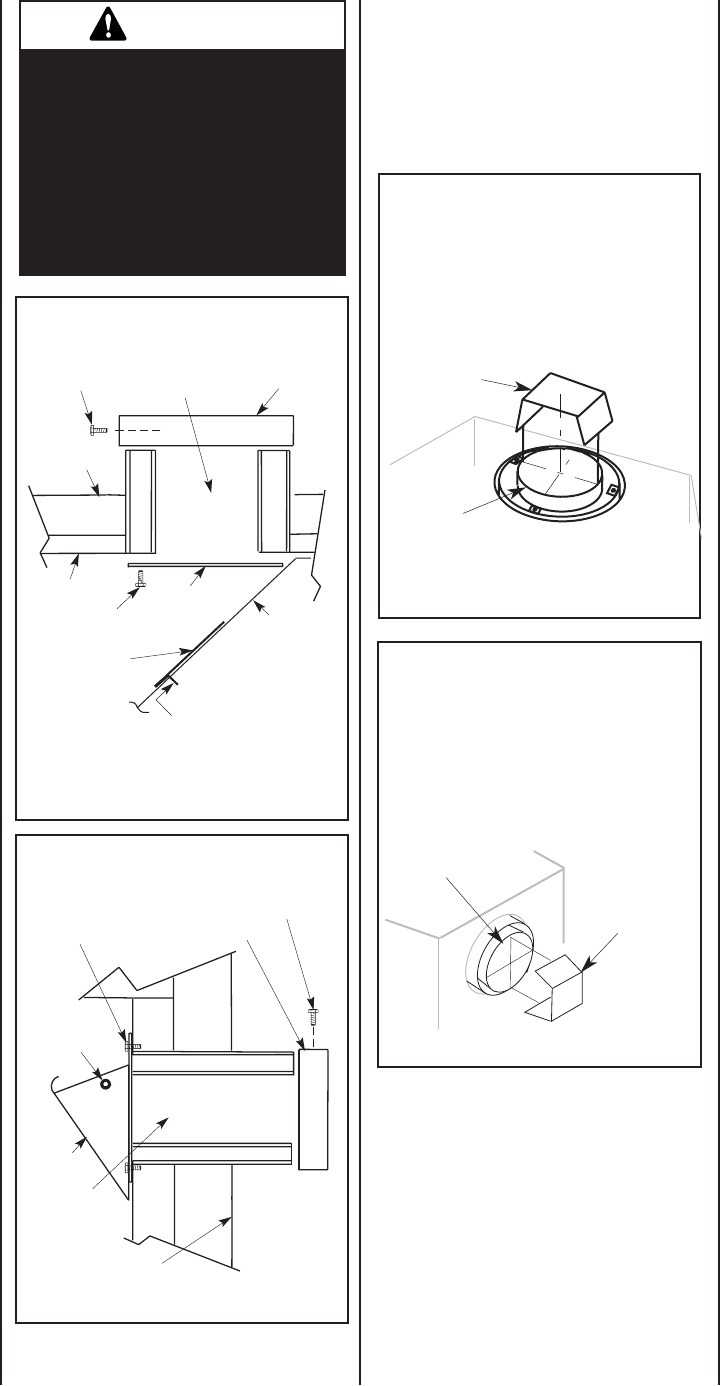
Inner Fireplace
Collar
Appliance Rear
Vent Outlet
Restrictor
REAR VENT
Restrictor Installation
If 3 ft. or more of vertical venting is used, install
a vent restrictor in the rear vent of the fi replace
outlet. It can be installed from the inside or
outside of the unit, in the inner fi replace collar.
It is held in place by friction only.
Figure 17b
WARNING
Failure to reinstall and securely
tighten cover plate screws could
result in leakage of fl ue products
into the living space. Vent cover
plate and vent seal plate must
remain securely installed on
unused vent collar. Failure to do
so could result in leakage of fl ue
products into living space.