


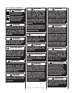

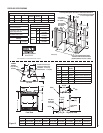

NOTE: DIAGRAMS & ILLUSTRATIONS ARE NOT TO SCALE.
3
New York City, New York (MEA)
Installation of these fi replaces are approved
for installation in New York City in the US state
of New York.
These appliances and their individual shut-off
valves must be disconnected from the gas
supply piping system during any pressure
testing of that system at pressures greater
than 1/2 psig (3.5 kPa).
These appliances must be isolated from the
gas supply piping system (by closing their
individual manual shut-off valve) during any
pressure testing of the gas supply piping
system at test pressures equal to or less than
1/2 psig (3.5 kPa).
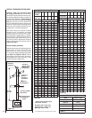
Orifi ce Sizes - Sea Level to High Altitude
(All Models)
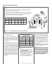
These appliances are tested and approved for
installation at elevations of 0-4500 feet (0-1372
meters) above sea level using the standard burner
orifice sizes (marked with an "*" in Table 7). For
elevations above 4500 feet, contact your gas
supplier or qualifi ed service technician . Install
the appliance according to the regulations of
the local authorities having jurisdiction and, in
the USA, the National Fuel Gas Code NFPA 54
/ ANSI Z223.1 - latest edition or, in Canada, the
CAN1-B149.1 and .2 codes - latest edition.
Input (BTU) Manually-Modulated Gas
Valves (millivolt models)
* PROPANE GAS
Models Input Rate (BTU / HR)
SDDV-35PM
27,000 high
20,700 low
SDDV-40PM
30,000 high
23,500 low
Table 2
Electronic Models
Electronic models have a fi xed rate gas valve.
Input of electronic models is shown in
Table
3.
Electronic Models with Fixed Rate Gas Valve
Natural and *Propane Gas
Model Series Input Rate (BTU / HR)
SDDV-35 27,000
SDDV-40 30,000
Table 3 * if fi eld converted
Inlet Gas Supply Pressure
(all models)
Fuel # Minimum Maximum
Natural Gas
5.0" WC
(1.24 kPa)
10.5" WC
(2.61 kPa)
Propane
11.0" WC
(2.74 kPa)
13.0" WC
(3.23 kPa)
Table 4
Gas Pressure - All Models
Tables 4, 5 and 6 show the appliances' gas
pressure requirements:
Manifold Gas Supply Pressure
(millivolt models)
Fuel # Low High
Natural
Gas
(Lo) 2.2" WC
(.55 kPa)
(Hi) 3.5" WC
(.87 kPa)
Propane
(Lo) 6.3" WC
(1.57 kPa)
(Hi) 10.0" WC
(2.49 kPa)
Table 5
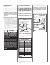
Test gauge connections are provided on the
front of the millivolt gas control valve, identi-
fi ed IN for the inlet and OUT for the manifold
side. A 1/8" NPT Test gauge connection
is provided at the inlet and outlet side of
the electronic gas control valve.
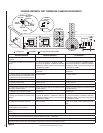
Burner Orifi ce Sizes
Elevation 0-4500 feet ( 0-1372 meters)
Model
Series
Natural
Gas
drill size
(inches)
Propane
Gas
drill size (inches)
SDDV-35
#40 (.098")
*
69L96 •
#53 (.0595")
*
39L10 •
SDDV-40
#36 (.1065")
*
18L40 •
#52
(.0635")
*
LB-55874D •
* Standard size installed at factory
• Part /Cat. Number
Table 7
Manifold Gas Supply Pressure
(electronic models)
Fuel # Max. Manifold Pressure
Natural Gas (Hi) 3.5" WC (.87 kPa)
Propane (Hi) 10.0" WC (2.49 kPa)
Table 6
* If fi eld converted - see Pages 34-36
Input (BTU) Manually-Modulated Gas
Valves (millivolt models)
NATURAL GAS
Models Input Rate (BTU / HR)
SDDV-35NM
27,000 high
21,000 low
SDDV-40NM
30,000 high
23,500 low
Table 1
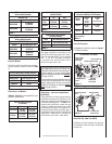
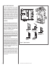
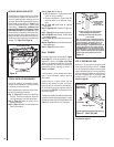
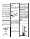
Figure 2
Honeywell Electronic Gas Valve
FFO
NI
PSI
NO
L
O
R
T
N
O
C
G
I
N
T
I
ER
Manifold Pressure
Port
ON / OFF Switch
Inlet
Pressure
Port
Electronic Gas
Control Valve
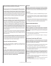
Gas Valve Diagrams
See Figure 1 for Millivolt models and Figure 2
For Electronic Models.
H
I
L
O
W
H
TPT
HT
P
T
P
I
L
O
T
P
I
L
O
T
O
N
it
O
F
F
IN
OUT
Manifold Pressure Tap
Inlet Pressure Tap
SIT Millivolt Gas Valve
Pilot Adjustment
Screw
HI/LO Variable
Flame Height
Adjustment
Main Gas
Control Knob
OFF/PILOT/ON
Figure 1