


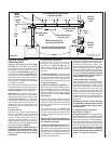
19
NOTE: DIAGRAMS & ILLUSTRA-
TIONS ARE NOT TO SCALE.
Horizontal / Inclined Run
Support Brackets
Building
Support
Framing
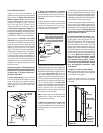
SV4.5E90
Elbow
Ceiling
Fireplace
SV4.5L6/12/24/36/48
Vent Sections
Vertical
Rise
SV4.5HT-2
Termination
Shown
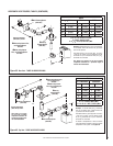
Support Bracket Spacing
Every 5 ft (1.52 m)
Exterior
Wall
SV4.5HT-2
Termination
Shown
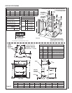
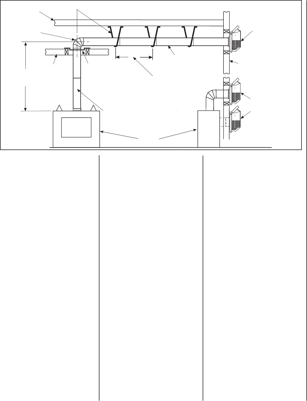
Figure 31
See Figure 18 on Page 14 or Figure 21 on
Page 15 for vertical vent section support.
TYPICAL HORIZONTAL VENT INSTALLATION
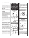
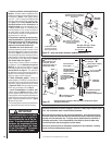
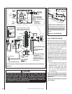
Firestop / Spacer
SV4.5VF
When Using Secure Flex,
Use Firestop / Spacer SF4.5VF
B. Frame exterior wall opening -
Locate the center of the vent outlet on
the exterior wall according to the dimen-
sions shown in Figure 13 on Page 10. Cut
and/or frame an opening, 10-1/2" x 12-1/8"
(267 mm x 308mm) inside dimensions, about
this center.
C. Frame ceiling opening - If the vertical route
is to penetrate a ceiling, use plumb line to locate
the center above the appliance. Cut and/or frame
an opening, 10-1/2" x 10-1/2" (267 mm x 267
mm) inside dimensions, about this center (refer
to Figure 19 on Page 15).
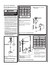
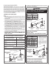
D. Attach vent components to appliance - To
attach a vent component to the appliance collar,
align the dimpled end over the collar, adjust-
ing the radial alignment until the four locking
dimples are aligned with the inlets of the four
incline channels on the collar (refer to Figure
20 on Page 15).
Push the vent component against the collar
until it fully engages, then twist the component
clockwise, running the dimples down and along
the incline channels until they seat at the end
of the channels.
The unitized design of the Secure Vent
components will engage and seal both the
inner and outer pipe elements with the same
procedure. Sealant and securing screws are
not required.
Note: An elbow may also be attached to the
appliance collar. Attach in the same manner
as you would a vent section.
E. Attach vent components to each other - Other
vent sections may be added to the previously in-
stalled section in accordance with the requirements
of the vent tables. To add another vent component
to a length of vent run, align the dimpled end of
the component over the inclined channel end of
the previously installed section,
adjusting the radial alignment until the four lock-
ing dimples are aligned with the inlets of the four
incline channels of the previous section. Push
the vent component against the previous section
until it fully engages, then twist the component
clockwise running the dimples down and along
the incline channels until they seat at the end of
the channels.This seating position is indicated
by the alignment of the arrow and dimple as
shown in Figure 20 on Page 15.
F. Install fi restop/spacer at ceiling -
When using Secure Vent, use SV4.5VF fi restop/
spacer at ceiling joists; when using Secure Flex,
use SF4.5VF fi restop/spacer. If there is living
space above the ceiling level, the fi restop/ spacer
must be installed on the bottom side of the
ceiling. If attic space is above the ceiling, the
fi restop/ spacer must be installed on the top side
of the joist. Route the vent sections through the
framed opening and secure the fi restop/spacer
with 8d nails or other appropriate fasteners at
each corner.
Remember to maintain 1" (25 mm) clearance
to combustibles, framing members, and attic
or ceiling insulation when running vertical
chimney sections.
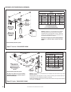
G. Support the vertical run sections -
See Section E on Page 15.
H. Change vent direction - At transition from or
to a horizontal/inclined run, install the SV4.5E45
and SV4.5E90 elbows in the same manner as
the straight vent sections. The elbows feature a
twist section to allow them to be routed about the
center axis of their initial collar section to align
with the required direction of the next vent run
element. Twist elbow sections in a clockwise
direction only so as to avoid the possiblity of
unlocking any of the previously connected vent
sections. See Figure 22 on Page 16.
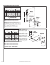
HORIZONTAL (OUTSIDE WALL)
TERMINATION SYSTEM
Figure 31, and Figures 34 to 40 on Pages
21 to 23 and their associated Horizontal Vent
Table illustrate the various horizontal venting
confi gurations that are possible for use with
these appliances. Secure Vent pipe applications
are shown in these Figures; Secure Flex pipe
may also be used. A Horizontal Vent Table sum-
marizes each system’s minimum and maximum
vertical and horizontal length values that can be
used to design and install the vent components
in a variety of applications.
Both of these horizontal vent systems terminate
through an outside wall. Building Codes limit or
prohibit terminating in specifi c areas. Refer to
Figure 6 on Page 8 for location guidelines.
Secure Vent SV4.5 direct vent system compo-
nents are unitized concentric pipe components
featuring positive twist lock connection, (refer
to Figure 20 on Page 15). All of the appli-
ances covered in this document are fi tted with
collars having locking inclined channels. The
dimpled end of the vent components fi t over
the appliance collar to create the positive twist
lock connection.
A. Plan the vent run -
Analyze the vent routing and determine the
types and quantities of sections required
4-1/2" (114 mm), 10-1/2" (267 mm), 22-1/2" (572
mm), 34-1/2" (876 mm) and 46-1/2" (1181 mm)
net section lengths are available. Plan the vent
lengths so that a joint does not occur at the inter-
section of ceiling or roof joists. Make allowances
for elbows as indicated in Figure 22.
Maintain a minimum 1" (25 mm) clearance to
combustibles on the vertical sections. Clear-
ances for the horizontal runs are; 3" (76 mm)
on top, 1" (25 mm) on sides, and 1" (25 mm)
at the bottom.