


NOTE: DIAGRAMS & ILLUSTRATIONS ARE NOT TO SCALE.
21
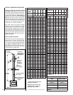
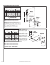
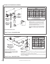
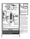
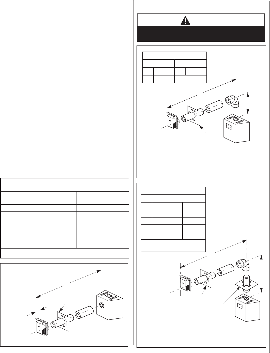
Figure 35 - Top Vent -
ONE 90 DEGREE ELBOW - ELBOW CONNECTION AT APPLIANCE
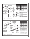
Figure 36 - Top Vent - ONE 90 DEGREE ELBOW -
ELBOW CONNECTION NOT DIRECTLY AT APPLIANCE
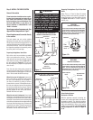
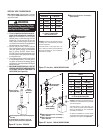
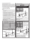
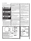
Figure 34 - Rear Vent - NO ELBOWS
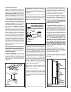
See Table 12 as an aid in venting component selection for a particular
range of exterior wall thicknesses.
See Table 12 as an aid in venting component selection
for a particular range of exterior wall thicknesses.
Notes:
• Secure Vent components (rigid vent pipe and terminal) are shown in
the Figures; Secure Flex components (fl exible vent pipe and terminal)
may also be used.
• Two 45 degree elbows may be used in place of one 90 degree elbow.
The same rise to run ratios, as shown in the venting Figures for 90
elbows,must be followed if 45 degree elbows are used.
• SV4.5VF (Secure Vent), SF4.5VF (Secure Flex) fi restop/spacer must be
used anytime vent pipe passes through a combustible fl oor or ceiling.
SV4.5HF (Secure Vent), SF4.5HF (Secure Flex) fi restop/spacer must
be used anytime vent pipe passes through a combustible wall.
• It is very important that the horizontal/inclined run be maintained
in a straight (no dips) and recommended to be in a slightly elevated
plane, in a direction away from the fi replace of 1/4" rise per foot (20
mm per meter) which is ideal, though rise per foot run ratios that are
smaller are acceptable all the way down to at or near level.
• The tables show a 1(V) to 5(H) ratio up to a maximum horizontal run
of 20 feet except for installations where an elbow is the only vertical
vent section in the system (see Figure 35).
• AN ELBOW IS ACCEPTABLE AS 1 FOOT OF VERTICAL RISE EXCEPT
WHERE AN ELBOW IS THE ONLY VERTICAL COMPONENT IN THE
SYSTEM. See Figure 35.
See Table 12 as an aid in venting component selection for a particular
range of exterior wall thicknesses.
WARNING
Under no circumstances, may separate sections of
concentric fl exible vent pipe be joined together.
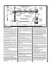
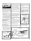
HORIZONTAL VENT FIGURES/TABLES
H
H = 28 in. (711 mm) Maximum.
7 in. (178 mm)
When using Secure Flex,
use Firestop/Spacer
SF4.5HF
Wall Firestop/Spacer
(SV4.5HF)
H
Wall
Firestop/Spacer
(SV4.5HF)
V
When using Secure Flex,
use Firestop/Spacer
SF4.5HF
H
V
Wall Firestop/Spacer
(SV4.5HF)
When using Secure Flex,
use Firestop/Spacer
SF4.5VF.
C
eiling
Firestop/Spacer
(SV4.5VF)
When using Secure Flex,
use Firestop/Spacer
SF4.5HF.
Venting Components Required for Various Exterior Wall Thick-
nesses, when using Square Termination Kit (SV4.5HT-2)
Vent Components Required
Exterior Wall Thickness
- inches (mm)
Termination Kit Only 6 to 9-1/4 (152 to 235)
Termination Kit and 6 In. Vent Section
(SV4.5L6)
10-1/2 to 13-3/4 (267 to 349)
Termination Kit and 12 in. Vent Section
(SV4.5L12)
16-1/2 to 19-3/4 (419 to 502)
Termination Kit & Telescopic Section (SV4.5LA
2 to 7-1/2") & 6" vent section (SV4.5L6)
11 to 19-3/4 (279 to 502)
Table 12
Example: If 20 feet of (H) hori-
zontal vent run is needed, then
4 feet minimum of (V) vertical
vent will be required.
This table shows a 1(V) to
5(H) ratio. For every 1 foot
of vertical, you are allowed 5
feet of (H) horizontal run up to
a maximum (H) horizontal run
of 20 feet.
Table G
H Maximum
V Minimum
feet (meter) feet (meter)
5 (1.524) 1 (0.305)
10 (3.048) 2 (0.610)
15 (4.572) 3 (0.914)
20 (6.096) 4 (1.219)
V + H = 40 feet (12.2 m) Max.
H = 20 ft. (6.096 m) Max.
Square termination
(SV4.5HT-2) shown.
Square termination
(SV4.5HT-2) shown.
Square termination
(SV4.5HT-2) shown.
Table F
H Maximum V Minimum
feet (meter) feet (meter)
3 (.914) Elbow Only
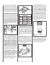
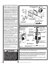
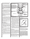
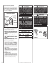
M. Install the Square Termination (SV4.5HT-2)
Install the square termination - For the last step , from outside the
exterior wall, slide the collars of the termination onto the adapter (the
outer inside the outer and the inner outside the inner) until the termina-
tion seats against the exterior wall surface to which it will be attached.
Orient the housing of the termination with the arrow pointed upwards.
Secure the termination to the exterior wall. The horizontal termination
must not be recessed into the exterior wall or siding by more than the
1-1/4" (32 mm) as shown in Figure 33.
Note: See Figure 33 showing wall thickness range
when using SV4.5HT-2 termination kit only.