


8
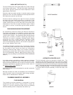
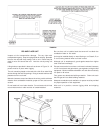
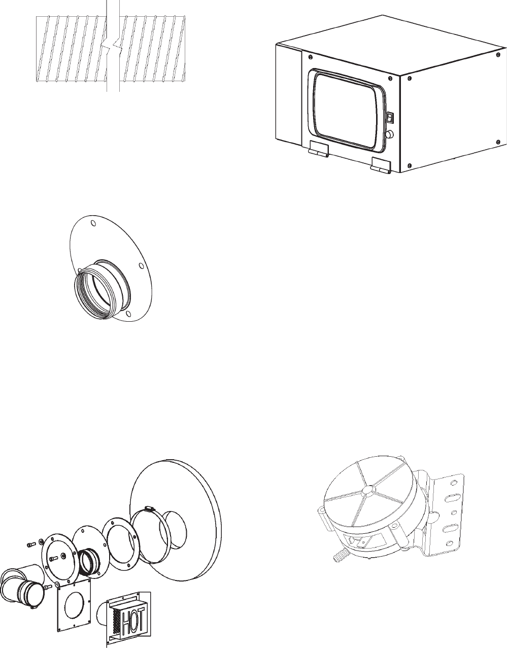
AIR HOSE
The air hose is used to provide a flexible air path from the blower
to the burner assembly. It is held in place with two standard hose
clamps, see Figure 10.
FIGURE 10
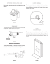
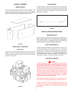
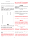
FLUE ADAPTER
The flue adapter is made of a flat metal plate with an exhaust
adapter to mate with the exhaust elbow. This is where the flue
gases exit the heat exchanger. This is a very hot region and is
covered with a layer of high temperature fiberglass insulation, see
Figure 11.
FIGURE 11
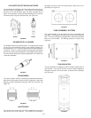
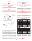
EXHAUST VENT
The exhaust vent elbow mates with the flue adapter. The elbow
mates with the exhaust terminal to dispose the flue gases to the
outdoors. This venting section is covered with a fiberglass
insulated wrap to protect from heat and condensation. These
pipes are sealed with a high temperature gasket integral to the
vent pipe fittings, see Figure 12.
FIGURE 12
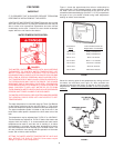
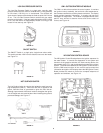
CONTROL SYSTEM
The control system is comprised of an Outdoor Interface Module
that monitors the functions of the WR ignition system, pressure
switches, low water cutoff and temperatures in the tank.
FIGURE 13
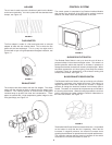
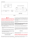
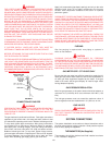
BLOCKED OUTLET SWITCH
The Blocked Outlet Switch is set up to shut the unit off when a
pressure buildup in the exhaust vent pipe occurs. This switch is a
positive pressure switch that requires an increase in pressure to
change the electrical contacts from normally closed to open. When
this switch prevents the unit from igniting, most likely the exhaust
is blocked. Check for obstructions in the exhaust venting and
exhaust vent terminal, see Figure 14.
BLOCKED INLET/PROVER SWITCH
The Blocked Inlet/Prover Switch is set up to shut the unit off when
a reduction in pressure in the intake vent occurs. This switch is a
negative pressure switch that requires an increase in negative
pressure to change the electrical contacts from normally open to
closed. The switch is connected to the pressure tap connected to
the housing of the blower. When this switch prevents the unit from
ignition, most likely the intake is blocked. Check for obstructions in
the inlet vent terminal, see Figure 14.
FIGURE 14
The blocked Inlet/Prover Switch has a second function. It is provided
on the heater to verify that the fan is operating. When the fan
increases in negative pressure, the electrical contacts close
signaling that the blower is operational and is at peak performance.
The controller requires that the electrical contacts on the switch
close before it will allow the blower to come on.