


34
NOTE: ANY BYPASS OR ALTERATION OF THE UNITS SAFETIES
WILL RESULT IN VOIDING THE APPLIANCE WARRANTY.
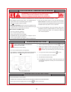
Before performing any troubleshooting familiarize yourself with
the particular appliance.
Refer to the SEQUENCE OF OPERATION on page 21 before
continuing.
Make sure the appliance is connected to a 120V AC power supply,
manual gas valve is in the ON position, and all electrical
connections are secure before continuing to troubleshoot this
appliance.
CAUTION
THE WATER HEATER IS POLARITY SENSITIVE. BEFORE
APPLYING ELECTRICITY TO THIS HEATER BE CERTAIN THAT
SUPPLY NEUTRAL WIRE TO GROUND CHECK INDICATES ZERO
VOLTAGE.
BLOWER MOTOR WILL NOT RUN
1. Confirm 120V AC to the controller. Also, to verify correct polarity,
check for 120 V AC between hot supply and ground.
If there is no voltage, check for a loose connection where it
connects to the controller.
2. If there is 120 volts to the controller, check for loose connections
or a locked rotor. If the rotor cannot be freed the motor and
blower assembly must be replaced.
MOTOR RUNS, PREPURGE TIME ELAPSES BUT MAIN
FLAME NOT ESTABLISHED.
1. Check to see if main manual gas valve is open.
2. Check for a loose connection at the transformer, or a defective
transformer.
3. Check for a loose connection at the gas valve.
4. Check for open pressure switches or open E.C.O. Check for
blockage in the intake and exhaust vent hoods. If no blockage
is found, check vinyl tubing for cuts or crimps. If this tubing is
damaged it must be replaced. If these steps do not eliminate
the problem, replace the pressure switches.
5. Check to see if there is resistance across the igniter terminal
with an ohmmeter. If there is no continuity, the igniter is broken
and should be replaced.
If the igniter appears to function properly, then verify that the inlet
pressure is 14" Natural Gas (3 kPa) maximum. The gas valve
supplied on this appliance is not designed to open against a
higher pressure. At this time also check that the inlet pressure
is not lower than the minimal gas supply pressure, as shown
in Table 4: that is, for Natural Gas, 6.2" W.C. If the inlet pressure
is not within these limits then adjust the supply pressure
accordingly.
If the inlet pressure falls within the allowable limits, then verify
that the manifold pressure, when the gas is fully open, with the
heater running, is as called out in Table 4: that is, 4.5" (1 kPa)
W.C. for Natural Gas. If the manifold pressure is not correct
then adjust accordingly. See ADJUSTMENT PROCEDURE in
OPERATING INSTRUCTIONS selection, page 21, for the
manifold pressure adjustment procedure.
6. If the inlet and manifold pressures are within the limits specified
in step 5, then reset the appliance. Verify 24V AC at the gas valve
during the three (3) second ignition trial, after the igniter reaches
operating temperature. If 24V AC at the gas valve is not seen
during this period, the controller must be replaced.
If there is 24V AC at the gas valve during the four second ignition
trial and the manifold pressure does not increase above 0"
W.C. then verify that the manual gas control valve is in the “ON”
position. If the valve is in the “ON” position and the previous
voltage and gas pressure conditions are met, then the gas
valve is defective and must be replaced.
Note that a positive manifold pressure reading of approximately
1.5" (.38 kPa) W.C. is normal during the prepurge portion of the
ignition cycle due to the location of the gas orifice.
MOTOR RUNS, BURNER LIGHTS MOMENTARILY,
THEN LOCKS OUT
1. Reset the appliance two more times to ensure that all of the air
has been purged from the gas line.
2. If the burner lights momentarily but does not sustain ignition,
verify that the inlet pressure is not greater than 14.0" (3.5 kPa)
W.C. or lower than the minimal gas supply pressure, as shown
in Table 4: that is, 6.0" for Natural Gas. Also, the manifold
pressure should rise during the three (3) second trial for
ignition. If the manifold pressure is not correct then adjust
accordingly. See ADJUSTMENT PROCEDURE in OPERATING
INSTRUCTIONS section, page 18, for the manifold pressure
adjustment procedure.
3. Check for the reversed polarity in the supply wiring. This
controller is polarity sensitive. If the hot and neutral supply wires
are reversed, the controller will not sense flame. Reverse the
supply wires and try to fire the unit.
NOTE: Always turn off and disconnect main supply wiring before
servicing the unit.
4. Check connecting wire to the flame sensor. Verify that the flame
sensor has not been damaged in any way.
5. Verify that the air supply is adequate. The air inlet screen or
blower wheel may be restricted. Also, check the installation for
proper ventilation. See AIR REQUIREMENTS.
6. Check the venting hoods for obstructions. See VENTING.
7. Check for a maximum inlet pressure of 14" Natural Gas (3
kPa), and the manifold pressure as listed in Table 4: that is, for
Natural Gas, 4.5". Please note that the manifold pressure listed
is the maximum value for the manifold pressure. Do not set the
manifold pressure higher than the value shown for your heater
in Table 4. Overfiring the heater will result in rough ignition and/
or noisy operation.
8. Confirm that the air inlet screen is free of obstructions.
CAUTION
Do not reach into the burner housing or combustion chamber if
the heater is still hot. Allow the heater to cool and always use
gloves as the combustion chamber and the burner sleeve and
housing can become very hot after operation. Overfiring is a
dangerous condition that must be corrected immediately.
GAS FAILS TO SHUT OFF
Check for defective gas valve or thermostat. If operation is incorrect,
replace.
REPLACEMENT PARTS
Replacement parts may be ordered through State dealers,
authorized servicers or distributors. Refer to the Yellow Pages for
where to call or contact the State Water Heaters, 500 Tennessee
Waltz Parkway, Ashland City, TN 37015, 1-800-821-2017. When
ordering parts be sure to state the quantity, part number and
description of the items including the complete model and serial
number as it appears on the product. Refer to the parts list for
more information.