


16
WARNING
THE HEATER IS NOT INTENDED FOR OPERATION AT HIGHER
THAN 14.0" WATER COLUMN (1/2 POUND OR 3.45 kPa PER
SQUARE INCH) SUPPLY GAS PRESSURE. HIGHER GAS SUPPLY
PRESSURES REQUIRE SUPPLEMENTAL REDUCING SERVICE
REGULATION. EXPOSURE TO HIGHER GAS SUPPLY PRESSURE
MAY CAUSE DAMAGE TO THE GAS CONTROLS WHICH COULD
RESULT IN FIRE OR EXPLOSION. IF OVERPRESSURE HAS
OCCURRED SUCH AS THROUGH IMPROPER TESTING OF GAS
LINES OR EMERGENCY MALFUNCTION OF THE SUPPLY SYSTEM
THE GAS VALVE MUST BE CHECKED FOR SAFE OPERATION.
MAKE SURE THAT THE OUTSIDE VENTS ON THE SUPPLY
REGULATORS AND THE SAFETY VENT VALVES ARE PROTECTED
AGAINST BLOCKAGE. THESE ARE PARTS OF THE GAS SUPPLY
SYSTEM, NOT THE HEATER. VENT BLOCKAGE MAY OCCUR
DURING ICE STORMS.
IT IS IMPORTANT TO GUARD AGAINST GAS VALVE FOULING FROM
CONTAMINANTS IN THE GAS WAYS. SUCH FOULING MAY CAUSE
IMPROPER OPERATION, FIRE OR EXPLOSION.
IF COPPER SUPPLY LINES ARE USED THEY MUST BE
INTERNALLY TINNED AND CERTIFIED FOR GAS SERVICE.
BEFORE ATTACHING THE GAS LINE BE SURE THAT ALL GAS
PIPE IS CLEAN ON THE INSIDE.
TO TRAP ANY DIRT OR FOREIGN MATERIAL IN THE GAS SUPPLY
LINE, A DIRT LEG (SOMETIMES CALLED A SEDIMENT TRAP OR
DRIP LEG) MUST BE INCORPORATED IN THE PIPING. THE DIRT
LEG MUST BE READILY ACCESSIBLE AND NOT SUBJECT TO
FREEZING CONDITIONS. INSTALL IN ACCORDANCE WITH
RECOMMENDATIONS OF SERVING GAS SUPPLIERS. REFER TO
THE
NATIONAL FUEL GAS CODE.
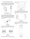
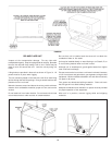
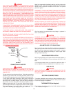
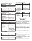
FIGURE 34
CONNECTION OF GAS PIPE
WARNING
PERFORM THE GAS LEAK TEST ANY TIME WORK IS DONE ON A
GAS SYSTEM TO AVOID THE POSSIBILITY OF FIRE OR
EXPLOSION WITH PROPERTY DAMAGE, PERSONAL INJURY OR
LOSS OF LIFE.
The gas leak test is performed as follows: Paint pipe connections
upstream of gas control with a rich soap and water solution to test
for leaks before operating main burner. Bubbles indicate gas leak.
To stop leak, tighten pipe connections. After piping connections
are checked, turn on main burner. With main burner in operation,
paint pipe joints (including flanges), pilot gas tubing connections
and control inlet and outlet with rich soap and water solution.
Bubbles indicate gas leak. To stop leak, tighten flange screws,
joints and pipe connections. Replace part if leak can’t be stopped.
To prevent damage, care must be taken not to apply too much
torque when attaching gas supply pipe to gas valve inlet.
Apply joint compounds (pipe dope) sparingly and only to the male
threads of pipe joints. Do not apply compound to the first two
threads. Use compounds resistant to the action of liquefied
petroleum gases.
DISCONNECT THE APPLIANCE AND ITS MANUAL GAS SHUTOFF
VALVE FROM THE GAS SUPPLY PIPING SYSTEM DURING ANY
SUPPLY PRESSURE TESTING EXCEEDING 1/2 PSIG (3.45 kPa).
GAS SUPPLY LINE MUST BE CAPPED WHEN DISCONNECTED
FROM THE HEATER. FOR TEST PRESSURES OF 1/2 PSIG (3.45
kPa). OR LESS, THE APPLIANCE NEED NOT BE DISCONNECTED,
BUT MUST BE ISOLATED FROM THE SUPPLY PRESSURE TEST
BY CLOSING THE MANUAL GAS SHUTOFF VALVE.
BEFORE PLACING THE HEATER IN OPERATION, CHECK FOR
GAS LEAKAGE. USE SOAP AND WATER SOLUTION OR OTHER
MATERIAL ACCEPTABLE FOR THE PURPOSE OF LOCATING GAS
LEAKS. DO NOT USE MATCHES, CANDLES, FLAME OR OTHER
SOURCES OF IGNITION FOR THIS PURPOSE.
PURGING
Gas line purging is required with new piping or systems in
which air has entered.
CAUTION
PURGING SHOULD BE PERFORMED BY PERSONS
EXPERIENCED IN THIS TYPE OF GAS SERVICE. TO AVOID RISK
OF FIRE OR EXPLOSION, PURGE DISCHARGE MUST NOT ENTER
CONFINED AREAS OR SPACES WHERE IGNITION CAN OCCUR.
THE AREA MUST BE WELL VENTILATED AND ALL SOURCES OF
IGNITION MUST BE INACTIVATED OR REMOVED.
GAS METER SIZE - CITY GASES ONLY
Be sure that the gas meter has sufficient capacity to supply the full
rated gas input of the water heater as well as the requirements of
all other gas fired equipment supplied by the meter. If the gas
meter is too small, ask the gas company to install a larger meter
having adequate capacity.
GAS PRESSURE REGULATION
Main line gas pressure to the water heater should be between a
maximum 14.0" (3.45 kPa). W.C. and a minimum of 6.2 W.C. (1.53
kPa).
The inlet gas pressure must not exceed the maximum value. A
service regulator must be installed within 10' (305 cm) of unit.
GAS VALVES
WARNING
SHOULD OVERHEATING OCCUR OR THE GAS SUPPLY FAIL TO
SHUT OFF, TURN OFF THE MANUAL GAS CONTROL VALVE TO
THE APPLIANCE.
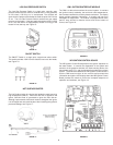
SYSTEM CONNECTIONS
The system installation must conform to these instructions and to
the local code authority having jurisdiction. Good practice requires
that all heavy piping be supported.
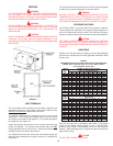
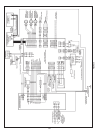
THERMOMETERS (Not Supplied)
Thermometers should be obtained and field installed as shown
in the installation diagrams.