


4
This design complies with the current edition of ANSI Z21.10.3 as
an automatic circulating tank type water heater and automatic
storage water heater.
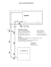
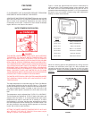
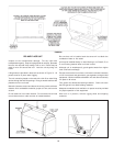
Detailed installation diagrams are found in this manual. These
diagrams will serve to provide the installer with a reference for the
materials and methods of piping necessary. It is highly essential
that all water, gas piping and wiring be installed as shown on the
diagrams.
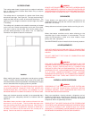
Particular attention should be given to the installation of
thermometers at the locations indicated on the diagrams as these
are necessary for checking the proper functioning of the heater.
In addition to these instructions, the equipment shall be
installed in accordance with all local codes. The authority
having jurisdiction should be consulted before installing.
In the absence of local codes, the installation must comply
with the current editions of the National Fuel Gas Code,
ANSI Z223.1/NFPA 54 and the National Electric Code, NFPA 70.
The former is available from the Canadian Standards
Association, 8501 East Pleasant Valley Road, Cleveland, OH
44131, and both documents are available from the National
Fire Protection Association, 1 Batterymarch Park, Quincy, MA
02269.
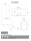
ROUGH-IN DIMENSIONS .................................................................... 2
INSTALLATION INFORMATION ........................................................... 3
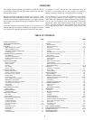
FOREWORD ....................................................................................... 4
FEATURES ......................................................................................... 5
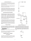
Water Temperature Control........................................................... 5
High Limit Switch (E.C.O.) ............................................................. 6
Dishwashing Machine Requirement ............................................. 5
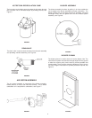
Circulating Pump ............................................................................ 6
PLUMBING MANIFOLD ASSEMBLY ................................................... 6
Flow Diagram ................................................................................ 5
Automatic Air Bleed Valve ............................................................ 5
Hot Return Recirculation Pump ..................................................... 7
Drain Valve .................................................................................... 7
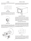
AIR SYSTEM ASSEMBLY .................................................................. 7
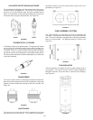
Blower Assembly.......................................................................... 7
Blower Plenum .............................................................................. 7
Air Hose ........................................................................................ 8
Flue Adapter .................................................................................. 8
Exhaust Vent ................................................................................. 8
CONTROL SYSTEM ........................................................................... 8
Blocked Outlet Switch .................................................................. 8
Blocked Inlet/Prover Switch.......................................................... 8
Low Gas Pressure Switch........................................................... 9
On/Off Switch............................................................................... 9
Hot Surface Igniter ........................................................................ 9
OIM - Outdoor Interface Module ................................................... 9
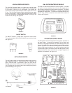
WR Ignition Control Board ............................................................. 9
Low Water Cutoff Board and Probe ............................................ 10
Thermostat/E.C.O. Probes ............................................................ 10
Transformer .................................................................................. 10
Junction Box ................................................................................. 10
TANK ASSEMBLY SYSTEM .............................................................. 10
Tank Insulation ............................................................................... 10
CABINET ASSEMBLY......................................................................... 11
Cabinet Panels .............................................................................. 11
ADDITIONAL CONTROLS .................................................................. 11
Gas Valve...................................................................................... 11
Flame Sensor ................................................................................ 11
INSTALLATION INSTRUCTIONS ......................................................... 11
Required Ability ............................................................................. 11
Insulation Blankets ........................................................................ 11
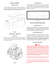
Locating The Heater...................................................................... 11-12
Provide Unit Support ..................................................................... 12
Roof Curb ...................................................................................... 12-13
Rig and Place Unit ......................................................................... 13
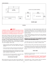
Outdoor Stand ............................................................................... 14
Clearances .................................................................................... 14
Hard Water .................................................................................... 14
Air Requirements .......................................................................... 14
FOREWORD
TABLE OF CONTENTS
Chemical Vapor Corrosion ............................................................ 14
VENTING ............................................................................................ 15
Vent Terminals............................................................................... 15
Pressure Switches....................................................................... 15
Gas Piping ..................................................................................... 15-16
Connection of Gas Pipe ................................................................ 16
Purging .......................................................................................... 16
Gas Meter Size - City Gases Only ............................................... 16
Gas Pressure Regulation.............................................................. 16
Gas Valves.................................................................................... 17
SYSTEM CONNECTIONS ................................................................... 17
Thermometers ............................................................................... 17
Relief Valve ................................................................................... 17
Water Line Connections ............................................................... 17
Closed System .............................................................................. 17
Water (Potable) Heating and Space Heating ................................ 17
Water Heater Wiring...................................................................... 17-18
OPERATION ........................................................................................ 19-20
Sequence of Operation ................................................................ 21
Error Codes ................................................................................... 21
Fault Conditions ............................................................................. 21-22
PRIOR TO START-UP ......................................................................... 22
Required Ability ............................................................................. 22
OPERATING INSTRUCTIONS .............................................................. 23
Adjustment Procedure (Initial Start-Up) ........................................ 23-24
Cathodic Protection ....................................................................... 24
Precautions ................................................................................... 24
Lighting & Operating Label............................................................ 25
GENERAL INFORMATION .................................................................. 26
Power Burner ............................................................................... 26
High Limit ....................................................................................... 26
High Altitude Installations .............................................................. 26
MAINTENANCE .................................................................................. 26
General.......................................................................................... 26
Maintenance Schedule ................................................................. 26
Flushing ......................................................................................... 26
Draining ......................................................................................... 26
Sediment Removal......................................................................... 26
Lime Scale Removal ...................................................................... 26-27
Anode Inspection and Replacement............................................. 27
Drain Valve and Access Panels ................................................... 27
Relief Valve ................................................................................... 27
Circulating Pump ............................................................................ 27
Vent System .................................................................................. 27
INSTALLATION DIAGRAMS ............................................................... 28-32
CHECKLIST AND SERVICE INFORMATION ........................................ 33
TROUBLE-SHOOTING........................................................................ 33-34
REPLACEMENT PARTS ...................................................................... 34
LIMITED WARRANTY ......................................................................... 35
PAGE PAGE