


6
HIGH LIMIT SWITCH (E.C.O.)
The top immersion well of the upper probe also contains the high
limit (energy cutoff) sensor. The high limit switch interrupts the
main burner gas flow should the water temperature reach
approximately 199°F/93°C.
Should the high limit switch activate, it must be reset by cycling
power to the unit. The water temperature must drop below 180°F/
82°C before the controller can be reset.
Continued manual resetting of the high limit control, preceded
by higher than usual water temperature is evidence of high
limit switch operation. For example, a malfunction of the control
system allowing the gas valve to stay open could cause water
temperature to rise until the high limit switch opens. Contact
your dealer or servicer if continued high limit switch operation
occurs.
DISHWASHING MACHINE REQUIREMENT
All dishwashing machines meeting the National Sanitation
Foundation requirements are designed to operate with water
flow pressures between 15 and 25 pounds per square inch
(103 kPa and 173 kPa). Flow pressures above 25 pounds per
square inch (173 kPa), or below 15 pounds per square inch
(103 kPa), will result in improperly sanitized dishes. Where
pressures are high, a water pressure reducing or flow
regulating control valve should be used in the 180°F (82°C)
line to the dishwashing machine, and should be adjusted to
deliver water between these limits.
The National Sanitation Foundation also recommends circulation
of 180°F (82°C) water. Where this is done, the circulation should
be very gentle so that it does not cause any unnecessary
turbulence inside the water heater. The circulation should be
just enough to provide 180°F (82°C) water at the point of take-
off to the dishwashing machine. Adjust flow by means of the
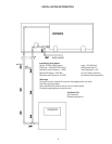
plug cock in the circulating line. (See INSTALLATION DIAGRAMS
section.)
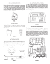
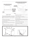
CIRCULATING PUMP
A circulating pump is used when a system requires a circulating
loop or there is a storage tank used in conjunction with the heater.
Refer to the piping diagrams at rear of manual for electrical hookup
information and install in accordance with the current version of
the National Electric Code NFPA No. 70.
All bronze circulators are recommended for use with commercial
water heaters.
Although circulators are oiled and operated by the manufacturer
some circulators must be oiled again before being operated.
Please refer to manufacturer's instructions.
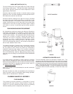
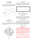
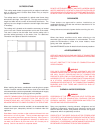
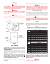
PLUMBING MANIFOLD ASSEMBLY
FLOW DIAGRAM
The plumbing manifold assembly is composed of several
components with each having a unique function. Please see
Figures 3, 5, and 6 to observe the water flow to the plumbing
manifold assembly and the components that make it up.
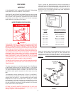
FIGURE 3
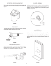
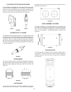
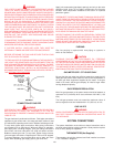
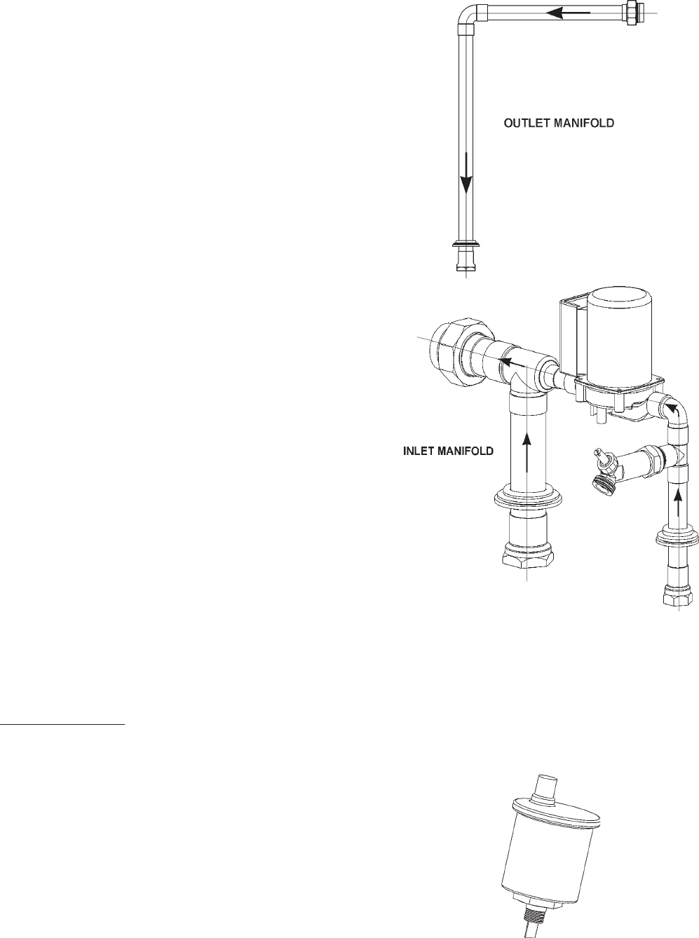
AUTOMATIC AIR BLEED VALVE
The tank assembly utilizes an automatic air bleed valve. The
purpose for this automatic air bleed valve is to allow air to escape
the tank when the unit is filled with water. When the unit is drained,
the opposite occurs with the valve allowing air to replace the drained
water. It removes the pressure vacuum that occurs in the system
causing incomplete drainage. This valve is automatic which allows
it to sense when the tank assembly is filled with water, see
Figure 4.
FIGURE 4