


15
VENTING
WARNING
THE INSTRUCTIONS IN THIS SECTION ON VENTING MUST
BE FOLLOWED TO AVOID CHOKED COMBUSTION OR
RECIRCULATION OF FLUE GASES. SUCH CONDITIONS CAUSE
SOOTING OR RISKS OF FIRE AND ASPHYXIATION.
WARNING
NEVER OPERATE THE HEATER UNLESS IT IS VENTED TO
THE OUTDOORS AND HAS ADEQUATE AIR SUPPLY TO AVOID
RISKS OF IMPROPER OPERATION, FIRE, EXPLOSION OR
ASPHYXIATION.
CAUTION
DO NOT TERMINATE THE VENTING WHERE NOISE FROM THE
EXHAUST OR INTAKE WILL BE OBJECTIONABLE. THIS
INCLUDES LOCATIONS CLOSE TO OR ACROSS FROM WINDOWS
AND DOORS.
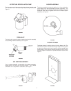
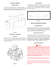
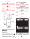
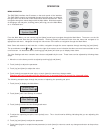
FIGURE 33
VENT TERMINALS
The vent system must terminate so that proper clearances are
maintained as cited in local codes or the current edition of the
National Fuel Gas Code, ANSI Z223.1/NFPA 54.
The SRT80-120NE series is designed with an internal vent
construction. The exhaust vent terminal and the inlet air terminal
are located on the sides of the appliance. Do not add vent pipe to
the appliance, see Figure 33.
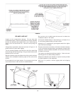
Assure the exhaust vent terminal is not in a public area where the
hoods are exposed. The exhaust vent terminal gets very HOT
during operation and can cause burns. Please use caution when
working around the exhaust vent terminal.
It is imperative that the area around the vent terminal hoods are
kept clear from obstructions so plenty of fresh air is available for
combustion.
The vent shall terminate a minimum of 12" (30.5 cm) above expected
snowfall level to prevent blockage of vent termination.
WARNING
USE ONLY THE VENT TERMINALS SUPPLIED WITH THIS UNIT.
TERMINATION OF A VENT SYSTEM WITH A DEVICE OTHER
THAN THE SUPPLIED VENT TERMINATIONS WILL AFFECT
SYSTEM PERFORMANCE AND RESULT IN A SAFETY HAZARD.
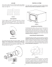
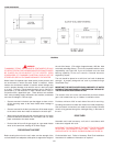
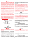
PRESSURE SWITCHES
The SRT80-120NE is provided with three pressure switches.
These switches are essential to the safe and proper operation of
the unit. All switches are wired in series. The controller is set up to
shut the unit down whenever there is a failure of any of the switches.
CAUTION
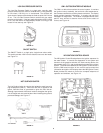
THE WATER HEATER IS POLARITY SENSITIVE. BEFORE
APPLYING ELECTRICITY TO THIS HEATER BE CERTAIN THAT
SUPPLY NEUTRAL WIRE TO GROUND CHECK INDICATES ZERO
VOLTAGE.
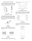
GAS PIPING
Contact your local gas service company to ensure that adequate
gas service is available and to review applicable installation codes
for your area.
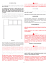
TABLE 3
MAXIMUM CAPACITY OF PIPE IN CUBIC FEET OF GAS PER HOUR
(Based upon a Pressure Drop of 0.5 inch Water Column
and 0.6 Specific Gravity Gas
Size the main gas line in accordance with Table 3. The figures
shown are for straight lengths of pipe at 0.5 in. (125 kPa) W.C.
pressure drop, which is considered normal for low pressure
systems. Note that fittings such as elbows and tees will add to the
pipe pressure drop.
CAUTION
DO NOT USE FLEXIBLE GAS PIPING.
LENGTH NORMAL IRON PIPE SIZES (INCHES)
IN INPUT IN THOUSANDS BTU/HR
FEET 1/2" 3/4" 1" 1 1/4" 1 1/2" 2" 2 1/2" 3" 4"
10 175 360 680 1400 2100 3960 6300 11000 23000
20 120 250 485 950 1460 2750 4360 7700 15800
30 — 200 375 770 1180 2200 3520 6250 12800
40 — 170 320 660 990 1900 3000 5300 10900
50 — 151 285 580 900 1680 2650 4750 9700
60 — 138 260 530 810 1520 2400 4300 8800
70 — 125 240 490 750 1400 2250 3900 8100
80 — — 220 460 690 1300 2050 3700 7500
90 — — 205 430 650 1220 1950 3450 7200
100 — — 195 400 620 1150 1850 3250 6700
125 — — 175 360 550 1020 1650 2950 6000
150 — — 160 325 500 950 1500 2650 5500
175 — — 145 300 460 850 1370 2450 5000
200 — — 135 280 430 800 1280 2280 4600
LENGTH NORMAL IRON PIPE SIZES (INCHES)
IN INPUT IN KW
METERS 1/2" 3/4" 1" 1 1/4" 1 1/2" 2" 2 1/2" 3" 4"
3.0 51 105 199 410 615 1160 1845 3221 6735
6.1 35 73 142 278 428 805 1277 2255 4626
9.1 — 59 110 225 346 644 1031 1830 3748
12.2 — 50 94 193 290 556 878 1552 3192
15.2 — 44 83 170 264 492 776 1391 2840
18.3 — 40 76 155 237 445 703 1259 2577
21.3 — 37 70 143 220 410 659 1142 2372
24.4 — — 64 135 202 381 600 1083 2196
27.4 — — 60 126 190 357 571 1010 2108
30.5 — — 57 117 182 337 542 952 1962
38.1 — — 51 105 161 299 483 864 1757
45.7 — — 47 95 146 278 439 776 1610
53.3 — — 42 88 135 249 401 717 1464
61.0 — — 40 82 126 234 375 688 1347