


21
SEQUENCE OF OPERATION
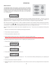
1. When the control is powered up the outdoor interface and the
remote interface should display a blank line and copyright on
the 2-line display.
2. After one second, the display should switch to indicate that the
touch switches are calibrating. During this process, the
Running LED will flash once per second until all of the switches
have been calibrated. This is an automatic process and can
take several seconds. Placing hands or fingers near the
switches can delay this process.
3. The control is now initialized and the display will change to
display the temperatures screen if no error is detected.
4. The system is checked for faults and, if detected, the Service
light will flash. If the fault is a temperature probe fault, the Service
LED will remain on without flashing. Whenever a fault is
detected, the display will switch to display the Current Error
screen.
5. If the control determines that the actual water temperature
inside the tank is below the programmed temperature setpoint
less the differential, a call for heat is activated. This call for heat
is generated even if the ignition module has detected an error,
however, if the ignition module has detected a fault, the ignition
sequence will not advance. Provided that no fault has been
detected, the Running LED will turn on.
6. If the Low-Water Cut-Off is satisfied, the ignition module will
then perform selected system diagnostic checks. This includes
confirming the proper state of the air switches and the ECO
limit device.
7. If all checks are successfully passed, the combustion blower
is energized for the pre-purge cycle.
8. When the pre-purge cycle is complete, power is applied to the
igniter element for the igniter warm-up period.
9. At the conclusion of the igniter warm-up period, the gas valve
will open, allowing gas to enter the burner chamber.
10. The igniter will remain on for a short predetermined time period,
then it will be turned off.
11. The control will monitor the flame sense probe to confirm a
flame is present. If a flame is not verified within the
predetermined flame prove time, the gas valve will immediately
be closed and the blower will continue to run for approximately
10 seconds. The control will then return to step 6.
12. If a flame is confirmed, the control will enter the heating mode
where it will continue heating the tank until the setpoint
temperature is reached. At this point, the gas valve is closed
and the control enters the post-purge cycle.
13. The combustion blower will run for the duration of the postpurge
cycle to purge the system of all combustion gasses. When the
post purge cycle is complete, the blower is deenergized and
will coast to a stop.
14. The control will now enter the standby state as indicated by the
Standby LED. The control will continue to monitor the tank
water temperature and the state of the other system devices. If
the temperature drops below the setpoint value less differential,
the control will automatically return to step 5 and repeat the
entire operating cycle. During this entire process, if the control
detects an improper operating state for external devices such
as the ECO switch, blower prover switch, etc., the appropriate
indication will be given on the interface modules.
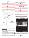
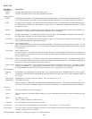
ERROR CODES
These error codes will be displayed if there is a problem with
ignition or operation of the heater. They will be displayed on the
LCD screen on the outdoor interface module and the remote
interface module.
The following error codes are codes related to the temperature
probes:
Outlet Probe
Tank Probe
The following error codes are related directly to the Ignition Module:
I.M. Lock Out
I.M. PS Closed
I.M. PS Open
I.M. ECO
I.M. 115V Reversed
I.M. Low Flame
I.M. Igniter
I.M. Flame Fault
Note: The ignition module faults are only reset after a one hour
delay period after the fault, or by cycling the power.
FAULT CONDITIONS
Fault: OUTLET PROBE
There is a problem with the outlet temperature probe
Possible Cause Remedy
1. Outlet temperature probe 1. Check that the temperature
is not connected (Wiring probe is connected properly
disconnect)
2. Outlet temperature probe 2. Repair wiring
wiring is open or closed
3. Defective outlet 3. Replace probe
temperature probe
Fault: TANK PROBE
There is a problem with the tank temperature probe
Possible Cause Remedy
1. Tank temperature probe is 1. Check that the temperature
not connected (Wiring probe is connected properly
disconnect)
2. Tank temperature probe 2. Repair wiring
wiring is open or closed
3. Defective tank temperature 3. Replace probe
probe