


9
BURNER
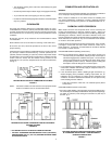
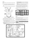
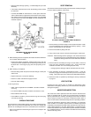
The burner assembly is mounted on the flange of the combustion chamber,
fig. 13.
NOTE: Be certain combustion chamber opening is aligned with opening
in heater flange, fig. 13, before placing burner into heater .
1. Place the flange gasket and combustion chamber seal over the burner
tube.
2. Place the burner flange on the studs and into the heater flange opening.
ASSEMBLY OF THE OIL BURNER TO THE HEATER
FIGURE 13
3. Place the flat washers and lock washers over the studs and fasten the
burner in place with the 3/8" - 16 nuts as shown.
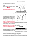
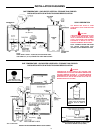
Connect the oil line(s) and electrical wires to the burner as follows:
1. The oil pump manufacturer's instructions should be checked for
connection and bleeding information.
• The burner is approved for use with fuel oil not heavier than No. 2.
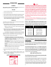
2. An approved, separately fused circuit with disconnect switch should
be available for the oil burner. Using Figure 14, the wiring diagram
below as a guide:
• Route the 120 volt incoming line in the dual bulb thermostat,
mounted on the side of the heater.
• Bring the factory wiring from the high limit /eco and thermostat into
the oil burner junction box.
• Install field and factory wiring as shown in the wiring diagrams,
figs. 14. A schematic diagram is also shown for convenience when
servicing.
• Ground the heater in accordance with the NEC code to guard
against electrical shock from the heater or water system.
3. All burners have "intermittent ignition" as defined by UL (ignition is on
during the time the burner is on and off when the burner is off).
4. Do not "test fire" the heater to complete the oil burner certificate until
the tank is filled with water, see the oil burner manual.
The certificate and this manual must be left with the user for future
reference.
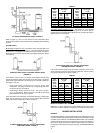
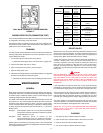
TABLE 8 - OIL PUMP & NOZZLE SPECIFICATIONS
Fitting Rate
(GPH) Oil Burner Oil Burner
Non Pump Oil Burner Nozzle
Heater State State Non-Setting Nozzle Rating
Model Burner Burner PSIG Spec. (GPH)
GPO 86 -199 1.42 1.1 110 1.35 x 80°B 1.35
GPO 86-245 1.75 1.5 100 1.75 x 80°B 1.75
GPO 84-315/315A 2.25 2.0 100 2.25 x 80°B 2.25
GPO 75-385/385A 2.75 2.5 100 2.75 x 80°B 2.75
GPO 75-455/455A 3.25 3.0 100 3.25 x 80°B 3.25
GPO 69-700/700A 5.00 4.5 100 5.00 x 80°B 5.00
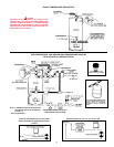
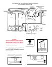
FUEL PUMP
GENERAL
All heaters are shipped with the pump pressure set at 100 psig except
the GPO 86-199 which is set at 110 psig.
All oil pumps are fitted for installation on single fuel line systems. The
pump may be adapted for two line service by using the by-pass Plug and
pump manufacturer's instructions packed with the burner.
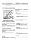
The single-stage pumps are for single-pipe or two-pipe installations, either
lift or gravity feed. On gravity feed installations the inlet pressure is not to
exceed 3 psig. On one pipe lift installations the lift is not to exceed 8 ft.
The two-stage pumps are for two-pipe lift installations where the inlet
vacuum does not exceed 20" hg. vacuum.
AIR BLEED PROCEDURE (Refer to oil burner manual).
FIGURE 14