


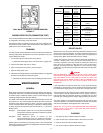

11
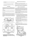
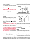
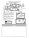
DUAL-BULB THERMOSTAT (COVER REMOVED)
FIGURE 17
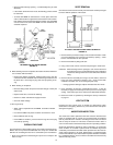
BURNER CERTIFICATE (COMBUSTION TEST)
The Commercial Standard CS75 Oil Burner Certificate form must be filled
in and posted in the vicinity of the water heater.
Instructions for filling in certificate are on the back of the certificate. This
must be done by the installer at the time the heater is first operated. The
certificate is in the oil burner manual.
DRAINING
The water heater must be drained if it is to be shut down and exposed to
freezing temperatures. Maintenance and service procedures may also
require draining the heater.
1. Turn off the oil burner electrical disconnect switch.
• If required for draining the heater, turn off the oil line supply valve.
2. Close the cold water inlet valve to heater.
3. Open a nearby hot water faucet to vent the system.
4. Open the heater drain valve.
5. If the heater is being drained for an extended shutdown, it is suggested
the drain valve be left open during this period.
• Following FILLING instructions when restarting hot water service.
MAINTENANCE
GENERAL
Water heater maintenance includes periodic tank flushing and cleaning,
and removal of lime scale. The oil burner should be inspected and adjusted
to maintain proper combustion. Where used, the water heating system
circulating pump should be oiled (See table 9).
The depth of lime buildup should be measured periodically. Heaters will
have about 2" (51 mm) of lime buildup when the level of lime has reached
the bottom of the cleanout opening or about 1" (25.4 mm) of lime buildup
if it has reached the drain valve opening. A schedule for deliming should
be setup, based on the amount of time it would take for a 1" (25.4 mm)
buildup of lime.
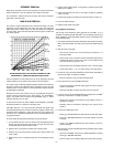
Example 1: Initial inspection shows 1/2" (12.7 mm) of lime accumulation
during the first 6 months of operation. Therefore, the heater
can be delimed once a year.
Example 2: Initial inspection shows 2" (51mm) of lime
accumulationduring the first 6 months of operation.
Therefore, the heater should be delimed every 3 months.
Following are the instructions for performing some of the recommended
maintenance. Oil burner inspection and adjustment should be performed
by a competent technician.
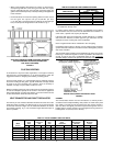
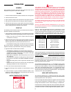
TABLE 9 SUGGESTED MAINTENANCE SCHEDULE
Semi-
Relief Valve Lift Lever Annually
Flushing Monthly
Sediment Semi-
Removal Annually
Anode Semi
Tank Inspection Annually
Lime Scale As UN•LIME
®
Removal Required Delimer
Circulating Four SAE No. 20 non-detergent
Pump Oiling Months motor oil
Inspection Combustion test
and Semi- kit & test specifications
Oil Burner Adjustment Annually (Page 26)
Nozzle Semi-
Replacement Annually New Nozzle
Flue Baffle
Pipe Cleaning Annually Wire Brush
Venting Semi-
System Inspected Annually
RELIEF VALVES
At least twice a year, the system relief valves should be checked to ensure
that they are in operating condition. To check a relief valve, lift the lever at
the end of the valve several times. The valve should seat properly and
operate freely. Water should flow while the lever is lifted.
If water does not flow, remove the valve and inspect for obstructions or
corrosion. Replace with a new valve of the recommended size as
necessary. Inspection of the valve should be performed at least every
three years. Do not attempt to repair the valve, as this could result in
improper operating and a tank explosion. In areas with poor water
conditions, it may be necessary to inspect the T&P valve more often than
twice a year.
DANGER
BEFORE MANUALLY OPERATING A RELIEF VALVE, MAKE SURE
THAT DRAIN LINE HAS BEEN ATTACHED TO THE VALVE TO DIRECT
THE DISCHARGE TO AN OPEN DRAIN. FAILURE TO TAKE THIS
PRECAUTION COULD MEAN CONTACT WITH EXTREMELY HOT
WATER PASSING OUT OF THE VALVE DURING THIS CHECK
OPERATION.
If the temperature and pressure relief valve on the heater discharges
periodically or continuously, it may be due to thermal expansion of water
in a closed water supply system, or it may be due to a faulty relief valve.
Thermal expansion is the normal response of water when it is heated. In
a closed system, thermal expansion will cause the system pressure to
build until the relief valve actuation pressure is equaled. Then, the relief
valve will open, allowing water to escape, slightly lowering the pressure.
Your water supplier or local plumbing inspector will know how to best
correct this situation. Two common corrections are listed in the Checklist
and Service Information which appears later in this manual.
ABOVE ALL, DO NOT PLUG THE TEMPERATURE AND PRESSURE
RELIEF VALVE. THIS IS NOT A SOLUTION AND CAN CREATE A
HAZARDOUS SITUATION.
FLUSHING
1. Turn off the oil burner electrical disconnect switch.
2. Open the drain valve and allow water to flow until it runs clean.
3. Close the drain valve when finished flushing.
4. Turn on the oil burner electrical disconnect switch.