


4
OIL BURNER SPECIFICATIONS
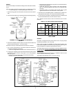
The oil burner nameplate decal includes a series code which identifies
the major features of the oil burner. The series number is the last three
digits of the burner code number.
Table 3 below describes the oil burner characteristics for each series
number. The burners are to be used with fuel oil not heavier than No. 2.
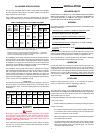
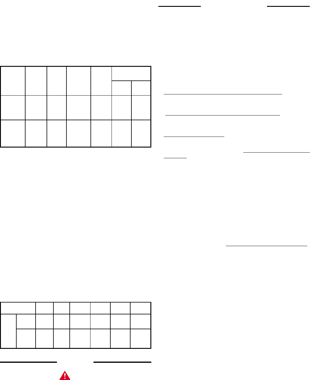
TABLE 3 SOME NOTABLE OIL BURNER FEATURES
R.W. Suntec Nozzle Type
State Becket Safety Oil Pump Oil
Burner Burner Timing Type Pump
Series Model + Mode Spray Spray
Number* Number Pattern Angle
A2VA
AFG 7118 Type B
940 15 Sec. Single - Solid 80°
SF Stage A2YA- Cone
7916
B2VA
8216 Type B
941 AFG 15 Sec. Two- - Solid 80°
SF 15 Sec. Stage BY2A Cone
8916
* To provide the proper firing rate for each model heater, see SPECIFICATIONS:
there are burner models for each heater model in table 2.
+ All oil burners are UL defined as having "interrupted ignition" . . . meaning the
ignition is on during the flame establishing period only. Ignition is off when the
burner is off. Standard safety timing is 15 seconds.
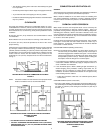
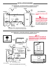
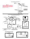
For installations where gravity feed of fuel oil from the storage tank to the
heater is practical, an oil burner with a single-stage oil pump can be used.
The 940 series of burners have single-stage pumps which are shipped
for installation of a supply line to the tank only. A return line back to the
storage tank can be installed, if required, by making a small modification
to the pump, see the oil burner installation manual.
For installations where gravity feed cannot be employed, (the storage
tank is located significantly below, or remote from, the heater) an oil burner
with a two-stage oil pump should be used. The 941 series of burners
have two-stage pumps which are shipped for installation of a supply and
return line to the tank. However, in situations where the return line is not
required (low lift installations), the pump may be modified to operate without
the line, see the oil burner installation manual.
IMPORTANT
The oil-fired water heater shipment consists of two packages, heater and
oil burner. Check to be certain the model number on the heater and oil
burner packages match. To assure matching equipment, see preceding
information.
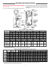
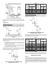
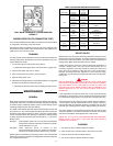
GPO 86 GPO86 GPO 84 GPO 75 GPO 75 GPO 69
Model Heater 199 245 315/315A 385/385A 455/455A 700/700/A
Min. State
Firing Burner 1.42 1.75 2.25 2.75 3.25 5.0
Rate
In Non
GPH State 1.1 1.5 2.0 2.5 3.0 4.5
Burner
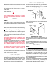
SAFETY
DANGER
BE SURE TO TURN OFF POWER WHEN WORKING ON OR NEAR
THE ELECTRICAL SYSTEM OF THE HEATER. NEVER TOUCH
ELECTRICAL COMPONENTS WITH WET HANDS OR WHEN
STANDING IN WATER. WHEN REPLACING FUSES ALWAYS USE THE
CORRECT SIZE FUSE FOR CIRCUIT.
If it is necessary to reset the safety primary control, depress red button
one time only. If burner does not operate after depressing red button
one time, call serviceman.
INSTALLATION
REQUIRED ABILITY
INSTALLATION OF SERVICE OF THIS WATER HEATER REQUIRES
ABILITY EQUIVALENT TO THAT OF A LICENCED TRADESMAN IN
THE FIELD INVOLVED. PLUMBING, AIR SUPPLY, VENTING , OIL
BURNER AND ELECTRICAL WORK REQUIRED.
GENERAL
The installer should be guided by these instructions, local codes and the
following publications.
•
Standards for the Installation of Oil Burning Equipment, NFPA
Standard No. 31, Available from National Fire Protection
Association, Batterymarch Park, MA 02269.
•
Code for the Installation of Heat Producing Appliances,
Available from American Insurance Association, 85 John Street,
New York, NY 10038.
• The National Electrical Code, ANSI/NFPA No. 70-1996. Availability
same as NFPA Standard No. 31-1997.
• In Canada - CSA Standard No. B139, Installation Code for Oil Burning
Equipment.
When other than a State burner is used, this instruction manual can be
used as a general guide. The burner manufacturer's instructions will have
to be consulted on specific questions of wiring, air adjustment, etc.
Do not test the burner or control system before the heater is filled with
water. Follow the START-UP procedure in this manual.
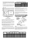
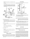
UNCRATING
Uncrate the heater by removing the outside mat and top locator. The
shipping pallet must be removed from the unit. It may be possible to
simply unbolt the base from the pallet and, with the help of two or more
persons, work the unit off the pallet. Some units will be too heavy and will
require the use of jacks or lifting equipment. Safely remove the pallet
and move the unit into position. Be Careful When Moving This Heater. It
will tip over easily.
LEVELLING
Install the heater plumb to the ground. If it is necessary to adjust the
heater, use metal shims under the channel type skid base.
LOCATION
The water heater should not be installed where the combustion air is
contaminated, see COMBUSTION AND VENTILATING AIR. Temperature
in the location must be above 32°F (0°C) and free of combustible dusts
and flammable gases or vapors.
For the best installations, the water heater should be located:
1. On a level surface.
• Shim the channel type skid base as necessary If leveling is required.
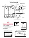
2. Near a floor drain.
• The heater should be located in an area where leakage of the tank
or connections will not result in damage to the area adjacent to the
heater or to lower floors of the structure.
• When such locations cannot be avoided, a suitable drain pan should
be installed under the heater.
• The pan should be at least two inches deep, have a minimum length
and width of at least two inches greater than the diameter of the
heater and should be piped to an adequate drain. The pan must
not restrict combustion air flow.