


21
If the problem is not getting a spark to ignite the oil, check for the following:
1. Loose wiring.
2. Red ignition transformer.
3. Low voltage.
4. Crack in electrode porcelain insulators.
5. Electrodes carboned or out of adjustment.
6. Weak or no contact between bus bars and terminals of transformer.
NORMAL START, BUT LOCKS OUT ON SAFETY
When the thermostat calls for heat and the burner starts normally but
then locks out on safety after about 15 seconds:
1. Improper setting of combustion air (too much air).
2. Weak or dirty flame detector.
3. Improper positioning of flame detector.
4. Bad flame detector.
5. Wiring from flame detector to primary not continuous or not making
good contact.
6. Bad safety primary control.
7. Clogged, defective or undersized nozzle.
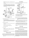
SAFETY PRIMARY CONTROL
Normal Burner Cycle
Although a normal burner cycle does not create a service problem, it is
important to know what happens to better understand the problem when
the unit is not operating properly.
The instant the thermostat calls for heat, the flame detector sees darkness
and causes the sensor to conduct current. When the sensor conducts
current, the motor relay coil pulls in, starting the burner motor and
energizing the ignition transformer through the motor relay contacts. At
the same instant the motor relay coil pulls in, the safety heater is energized.
When flame is established, the resistance of the flame detector drops
(providing the flame detector can see the flame properly) which causes
the sensor to block the current. When the sensor blocks, the safety
heater drops out of the circuit and the motor relay coil continues to hold in
through a set of holding contacts on the motor relay until the thermostat
is satisfied and the burner shuts down.
FLAME FAILURE AFTER NORMAL IGNITION
If, for some reason, there is a flame out, the flame detector sees darkness
which causes the sensor to conduct current and again energize the safety
heater. In approximately 15 seconds the safety contact will open and
shut down the burner. The safety contacts of the safety primary control
are the manual reset type, which means that the red safety button must
be reset before trying again for ignition. When this occurs, allow about 5
minutes for safety heater to cool before depressing the red safety button.
Depress red button one time only. If burner does not operate after
depressing red button one time, check combustion chamber. If
combustion chamber is soaked with oil the combustion chamber must be
replaced.
Some of the possible reasons for flame failure after normal ignition has
occurred are:
1. Dirt or water in the supply line.
2. Pump loosing prime.
3. Bad motor.
4. Erratic or low pressure at fuel pump.
5. Defective pump.
6. Loose wiring or connections.
7. Clogged or damaged nozzle.
8. Oil tank empty.
9. Oil tank not vented.
10.Clogged filter in oil line.
11. Ice in fuel line.
COMBUSTION TEST
SPECIFICATIONS
GENERAL
A combustion test kit, capable of testing CO
2
content, stack temperature,
draft and smoke must be available to aid in adjusting the unit and filling
out the Oil Burner Certificate. A pressure gauge is needed to measure
and adjust oil pump pressure.
PROCEDURE
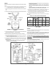
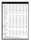
1. Check nozzle size, see Table 8 on Page 9.
2. Open air band about halfway and being certain heater is filled with
water, start burner.
3. Check oil pump pressure. It should be 110 psig for the GPO-199 and
100 psig for all other models. Adjust setting as necessary.
4. Allow burner to operate for 15 minutes before proceeding with test.
5. After 15 minutes operation, check the draft in chimney connector,
about halfway between the heater and the draft regulator and adjust
the draft regulator until the correct reading is obtained.
Draft in Chimney .03 to .05
Connector Inches of Water
6. Adjust air band until flame has smoky tips. Immediately increase air
supply until the smoky tips just disappear.
7. Using combustion test kit, check smoke density and CO
2
in the chimney
connector.
Preferably No. 1 Spot
Smoke Density (Not Over No. 2 Spot
CO
2
9% to 12%
• Adjust air supply with air band to achieve the highest CO
2
readings
with an acceptable smoke density reading. Test and readjust as
necessary.
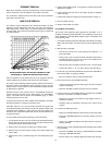
8. Check the stack temperature halfway between the heater and the
draft regulator.
Min. 400°F (204°C)
Max. 600°F (315°C)
• If stack temperature is too high, check for a soot accumulation in
heater or excessive oil pump pressure.
9. Recheck combustion efficiency against specifications when final
adjustments have been made.
Stack
Temperature