


8
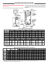
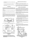
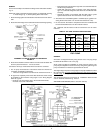
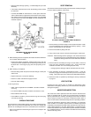
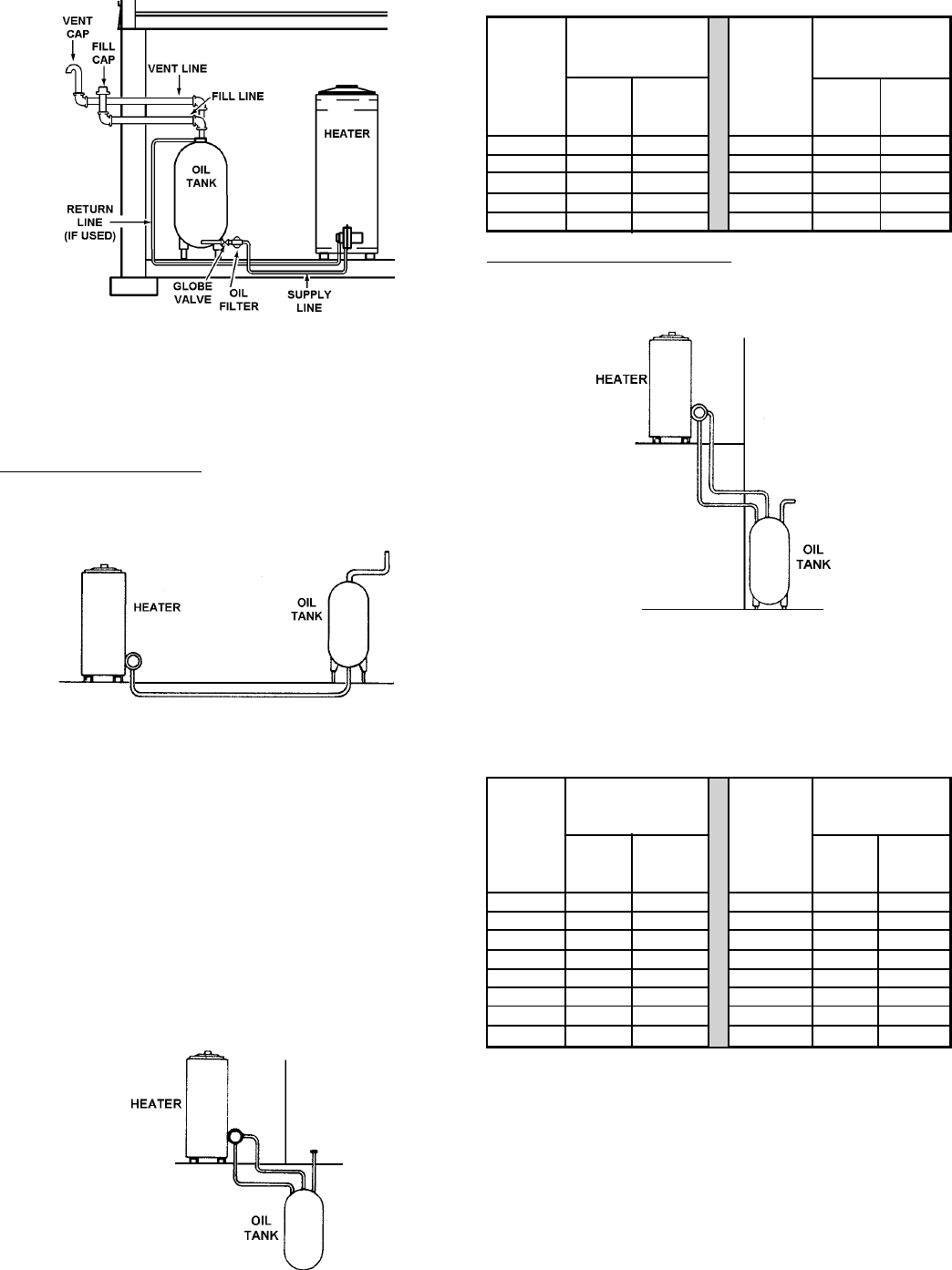
A TYPICAL HEATER INSTALLATION - FIGURE 9
Refer to pages 2, 3, and 4 in this manual for more information about
burner series numbers and characteristics for adaptability to the following
systems.
SYSTEM TYPES
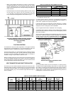
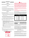
Single Stage, Supply Line Only: The bottom of the oil storage tank must
be above the level of the fuel unit, fig. 10. The fuel oil will flow by gravity
to the burner. A single pipe is run between the tank and fuel unit. Burner
Series No. 940 is from this type of service as shipped (the bypass plug is
not installed).
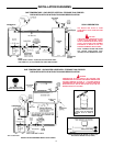
A GRAVITY FEED, SUPPLY LINE ONLY, INSTALLATION
FIGURE 10
If the bottom of the oil tank is at least 2 inches higher than the plug
opening at which the supply line connects to the fuel pump, a single-line
gravity-feed system with 3/8" O.D. tubing may be used with a maximum
run length of 100 feet.
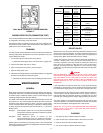
• A two stage pump may be used on one line, gravity feed
installations. The pump will function as a single stage unit when
the by-pass plug is not installed.
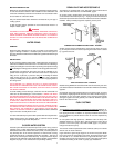
• Single Stage, Supply and Return Lines. This type of system,
fig. 11, is self-priming. Burner Series No. 940 with by-pass plug
field installed, is for this type of service.
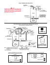
If the tank bottom is no lower than 10 feet below the plug, a single stage
pump may be used but, it must be a two line system with maximum
tubing runs (which includes lift) as shown in Table 6.
A SINGLE STAGE (LOW LIFT), SUPPLY AND RETURN
LINE INSTALLATION - FIGURE 11
TABLE 6
Distance Max. Distance Max.
Tank Run length Tank Run Length
Bottom Ft. (M) Bottom Ft. (M)
Below Below
Pump 3/8" 1/2" Pump 3/8" 1/2"
Plug O.D. O.D. Plug O.D. O.D.
Ft. (M) Tubing Tubing Ft. (M) Tubing Tubing
1 (0.3) 66 (20.1) 100 (30.4) 6 (1.8) 36 (10.9) 100 (30.4)
2 (0.6) 55 (16.7) 100 (30.4) 7 (2.1) 31 (9.4) 100 (30.4)
3 (0.9) 50 (15.2) 100 (30.4) 8 (2.4) 26 (7.9) 100 (30.4)
4 (1.2) 45 (13.7) 100 (30.4) 9 (2.7) 21 (6.4) 83 (25.2)
5 (1.5) 40 (12.1) 100 (30.4) 10 (3.0) 16 (4.8) 64 (19.5)
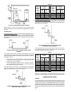
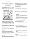
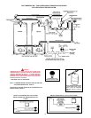
Two Stage, Supply and Return Lines: This system, fig. 12, is required
when long lines and high lifts (requiring up to 20" of vacuum and 10'
vertical lift) are encountered. Burner Series No. 941 is used in this service.
Bypass plug must be installed.
A TWO STAGE (HIGH LIFT), SUPPLY AND RETURN
LINE INSTALLATION - FIGURE 12
If the tank(s) bottom is lower than the plug by more than 10 feet, a two
stage pump with a two line system must be used with maximum tubing
runs (which includes lift) as shown in Table 7.
TABLE 7
Distance Max. Distance Max.
Tank Run length Tank Run Length
Bottom Ft. (M) Bottom Ft. (M)
Below Below
Pump 3/8" 1/2" Pump 3/8" 1/2"
Plug O.D. O.D. Plug O.D. O.D.
Ft. (M) Tubing Tubing Ft. (M) Tubing Tubing
1 (0.3) 74 (22.5) 100 (30.4) 9 (2.7) 51 (15.5) 100 (30.4)
2 (0.6) 71 (21.6) 100 (30.4) 10 (3.0) 48 (14.6) 100 (30.4)
3 (0.9) 69 (21.0) 100 (30.4) 11 (3.3) 45 (13.7) 100 (30.4)
4 (1.2) 66 (20.1) 100 (30.4) 12 (3.6) 42 (12.8) 100 (30.4)
5 (1.5) 63 (19.2) 100 (30.4) 13 (3.9) 39 (11.8) 100 (30.4)
6 (1.8) 60 (18.2) 100 (30.4) 14 (4.2) 37 (11.2) 100 (30.4)
7 (2.1) 57 (17.3) 100 (30.4) 15 (4.5) 34 (10.3) 100 (30.4)
8 (2.4) 54 (16.4) 100 (30.4)
MULTIPLE HEATER FUEL LINES
Where two or more heaters form a water heating system, each burner
shall have an entirely separate oil supply line from the tank to the burner.
BURNER INSTALLATION
GENERAL
An oil Burner Certificate is packed with the oil burner. Following the burner
manual installation the necessary tests shall be performed and the results
recorded on the certificate, see BURNER CERTIFICATE. The certificate
and this instruction manual must be left with the user for future reference.
Check to be certain the heater and burner model numbers are alike and
the oil pump characteristics are proper for the job. See IDENTIFICATION,
page 3.