


10
OPERATION
GENERAL
Never operate the heater unless the tank is filled with water and a
temperature and pressure relief valve is installed.
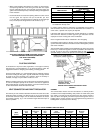
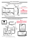
FILLING
1. Oil burner electrical disconnect switch should be in the "OFF position
2. Close the heater drain valve.
3. Open a nearby hot water faucet to allow the air in the system to escape.
4. Fully open the cold water inlet valve, filling the heater and piping.
5. Close the hot water faucet as water starts to flow from the opening,
Leave the cold water inlet valve fully open. The heater is now ready to
start-up if being placed in operation for the first time.
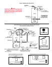
START-UP
The following checks should be made by the installer when the heater is
placed into operation for the first time:
1. Check all factory and field made water, oil and electrical connections
for tightness. Also check flue gas disposal provisions on top the heater.
• Repair any water and oil leaks. Tighten electrical and flue
connections as necessary.
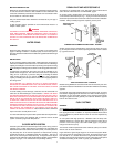
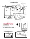
2. Where the water heater or water heating systems includes a circulating
pump, it may need to be lubricated before operated. The tube of
lubricant supplied with the pump includes directions for use.
• Field installed circulating pumps should be all bronze construction.
Be sure the oil burner, related piping, valves and controls are in place,
adjusted and ready for operation before turning on the electricity.
3. Adjust the heater mounted control as follows:
• THERMOSTAT (adjustable) set for desired water temperature.
• It is suggested the thermostat be turned to the lowest setting which
satisfies the hot water requirements of the system. This helps
minimize scale formation in the heater.
• HIGH LIMIT (not adjustable, manual reset) factory set to cutout at
195° F (90.5°C).
• If the high limit is actuated, the safety primary control will cause
the oil burner to shut down. See SAFETY PRIMARY CONTROL,
page 21.
• To reset the safety primary control, depress the red button on the
control.
• Depress red button one time only. If burner does not operate after
depressing red button one time, call service man.
4. Turn on the oil burner electrical disconnect switch.
5. The heater will begin normal operation on the thermostat's "call for
heat".
6. To turn the heater off, open the electrical disconnect switch. If the
heater is to remain inoperative for a long period of time, close the
shutoff valve on the oil supply line.
WATER TEMPERATURE CONTROL
DANGER
THIS WATER HEATER IS EQUIPPED WITH AN ADJUSTABLE
THERMOSTAT TO CONTROL WATER TEMPERATURE. HOT WATER
TEMPERATURES REQUIRED FOR AUTOMATIC DISHWASHER AND
LAUNDRY USE CAN CAUSE SCALD BURNS RESULTING IN SERIOUS
PERSONAL INJURY AND OR DEATH. THE TEMPERATURE AT WHICH
INJURY OCCURS VARIES WITH THE PERSONS AGE AND TIME OF
EXPOSURE. THE SLOWER RESPONSE TIME OF CHILDREN, AGED
OR DISABLED PERSONS INCREASES THE HAZARDS TO THEM.
NEVER ALLOW SMALL CHILDREN TO USE A HOT WATER TAP, OR
TO DRAW THEIR OWN BATH WATER. NEVER LEAVE A CHILD OR
DISABLED PERSON UNATTENDED IN A BATHTUB OR SHOWER.
THE WATER HEATER SHOULD BE LOCATED IN AN AREA WHERE
THE GENERAL PUBLIC DOES NOT HAVE ACCESS TO SET
TEMPERATURES.
SETTING THE WATER HEATER TEMPERATURE AT 120°F (48.9°C)
WILL REDUCE THE RISK OF SCALDS. Some states require settings at
specific lower temperatures.
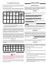
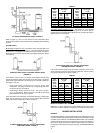
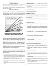
Figure 16 shows the approximate time-to-burn relationship for normal
adult skin. Short repeated heating cycles caused by small hot water
uses can cause temperatures at the point of use to exceed the thermostat
setting by up to 20°F. If you experience this type of use, you should
consider using lower temperature settings to reduce scald hazards.
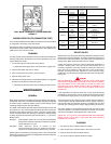
Temperature Time to Produce 2nd & 3rd
Setting Degree Burns on Adult Skin
180°F (82.2°C) Nearly instantaneous
170°F (76.6°C) Nearly instantaneous
160°F (71.1°C) About 1/2 second
150°F (65.5°C) About 1-1/2 seconds
140°F (60.0°C) Less than 5 seconds
130°F (54.4°C) About 30 seconds
120°F (48.9°C) More than 5 minutes
FIGURE 16
Values for reducing point-of-use temperature by mixing cold and hot water
are available. Also available are inexpensive devices that attach to faucets
to limit hot water temperatures. Contact a licensed plumber or the local
plumbing authority.
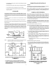
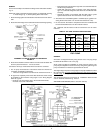
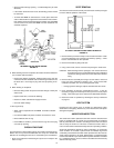
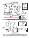
The water temperature is controlled by a thermostat, fig. 17, which has
two sensing elements. One sensor is located near the top of the tank and
the other is near the center. The thermostat is set in the lowest position
before the heater leaves the factory.
The thermostat temperature dial, fig. 17, is accessible by taking off the
access cover and removing the control cover. The dial is adjustable and
may be set for 120°F (48.9°C) to 170°F (76.6°C) water temperature, but
120°F is the recommended starting point. It is suggested the dial be
placed in the lowest setting which produces an acceptable hot water supply.
This will always give the most energy efficient operation. The temperature
control has a 4F° (2.2C°)fixed differential.
HIGH LIMIT SWITCH (E.C.O)
The dual bulb controller (fig.17) contains the high limit (energy cutoff)
sensor. The high limit switch interrupts main burner gas flow should the
water temperature reach 195°F (90.5°C).
In the event of high limit switch operation, the appliance cannot be restarted
unless the water temperature is reduced by 20F° (11.1C°) (approx.) and
the high limit reset button on front of limit control (fig.17) is depressed.
Continued manual resetting of high limit control, preceded by higher than
usual water temperature is evidence of high limit switch operation. Contact
your dealer or servicer if continued high limit switch operation occurs.