


7
MULTIPLE HEATER FLUES
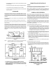
When two or more oil-fired water heaters are connected to a single chimney
or vent there shall be sufficient draft available for safe combustion and
removal of combustion products to the outdoors from each heater. Refer
to local codes for connection details.
Only one oil-fired water heater should be connected to any one type L
venting system.
A draft regulator shall be provided for each oil-fired water heater in a
multiple heater system.
DANGER
INCORRECT INSTALLATION CAN CAUSE IMPROPER OPERATION,
FIRE, ASPHYXIATION, SERIOUS PERSONAL INJURY OR DEATH.
NEVER OPERATE THIS WATER HEATER UNLESS IT IS PROPERLY
VENTED TO THE OUTDOORS AND HAS ADEQUATE COMBUSTION
AIR SUPPLY.
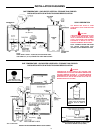
WATER PIPING
GENERAL
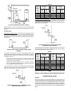
Select the piping diagram for the type of system to be installed from
pages 14 through 18. When a circulation pump is used in the system a
plug cock should be installed where indicated to regulate water flow through
the heater.
RELIEF VALVE
An A.G.A. design-certified and A.S.M.E.-rated temperature and pressure
relief valve is installed in the water heater . The relief valve has a discharge
capacity exceeding the maximum heater input rating and a pressure rating
not exceeding the working pressure shown on the rating plate of the heater.
A temperature and pressure relief valve must also be installed on any
potable water storage tank. This relief valve should have a temperature
rating of 210° F (98.9°C), a pressure rating not exceeding the lowest
rated working pressure of any system component, and a discharge
capacity exceeding the total input of the water heaters supplying water to
the storage tank.
THE PURPOSE OF A RELIEF VALVE IS TO AVOID EXCESSIVE
PRESSURE OR TEMPERATURE INTO THE STEAM RANGE, WHICH
MAY CAUSE SCALDING AT FIXTURES, TANK EXPLOSION, SYSTEM
OR HEATER DAMAGE.
To avoid scalding or water damage, a drain line must be connected to a
relief valve to direct discharge to a safe location, A DRAIN LINE MUST
NOT BE REDUCED FROM THE SIZE OF THE VALVE OUTLET AND IT
MUST NOT CONTAIN ANY VALVES BETWEEN THE HEATER AND THE
RELIEF VALVE OR THE RELIEF VALVE AND THE DRAIN LINE EXIT.
IN ADDITION, THERE SHOULD NOT BE ANY RESTRICTIONS IN A
DRAIN LINE NOR SHOULD IT BE ROUTED THROUGH AREAS WHERE
FREEZING CONDITIONS MIGHT OCCUR. DO NOT THREAD OR CAP
THE DRAIN LINE EXIT. RESTRICTING OR BLOCKING A DRAIN LINE
WILL DEFEAT THE PURPOSE OF THE RELIEF VALVE AND MAY
CREATE AN UNSAFE CONDITION. Install a drain line with a downward
slope such that it naturally drains itself.
Your local code authority may have other specific relief valve requirements.
NOTE: These heaters are equipped with an automatic burner shutoff
system actuated by high water temperature.
CLOSED WATER SYSTEM
A closed system will exist if a back-flow preventer (check valve), pressure
reducing valve, or other similar device is installed in the cold water line
between the water heater and the street main (or well). Excessive pressure
may develope due to the thermal expansion of heated water causing
premature tank failure or intermittent relief valve operation. This type of
failure is not covered by the limited warranty. An expansion tank may be
necessary in the cold water supply to alleviate this situation, see installation
diagrams on pages 14-18. Contact the local plumbing authority.
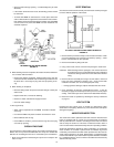
DRAIN VALVE AND ACCESS PANELS
The heaters are equipped with a 3/4" NPT drain valve mounted above
and to the left of the oil burner, see FEATURES, page 2.
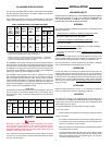
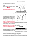
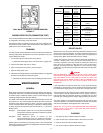
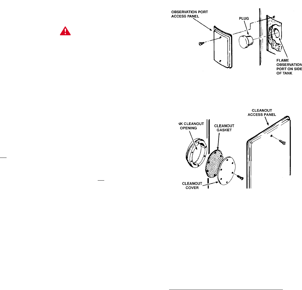
An access panel is located above and to the left of the oil burner and
covers the flame observation port, fig. 7. A plug is inserted into the flame
observation port and must be removed in order to look into the combustion
chamber. Always reinstall plug before replacing access panel.
COMBUSTION CHAMBER ACCESS PORT - FIGURE 7
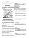
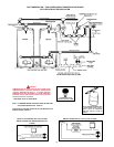
Another access panel is located above and to the right of the oil burner,
fig. 8. This panel covers the cleanout opening in the tank which is sealed
by a gasket and cover.
TANK CLEANOUT PORT - FIGURE 8
Models having ASME tank construction will have two cleanout ports. One
port will be located as indicated above and the other will be located directly
opposite.
Occasionally, some water seepage will occur at a cleanout port. To correct
this situation, slightly tighten the cleanout cover bolts until the seepage is
eliminated. Do not over tighten the bolts or the cleanout gasket will be
damaged. Tighten each bolt gradually and alternate between opposed
bolts on the cleanout cover.
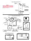
FUEL SYSTEMS
GENERAL
The Standard for the Installation of Oil Burning Equipment-NFPA No. 31,
local codes, and these instructions must be followed when installing the
tank, piping and burner. In addition, an oil pump installation sheet and oil
burner certificate are packed with the burner for use and completion by
the installer.
On fuel systems with high pressures, a Webster "OSV" oil safety valve
(Webster Electric CO., Racine, Wisc.) will be required to reduce the oil
pressure at the burner pump. See FUEL PUMP, page 9, for pressure
ratings of the burner's pump.
This manual and the completed oil burner certificate (CS75) are to be left
with the user for future reference.
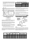
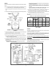
Figure 9 shows a typical single stage one or two line fuel system. When
two or more tanks are connected to one burner, the supply line from each
tank should run to a header fitted with an approved three-way valve.
Normally only one tank may be drawn at a time unless local codes permit
simultaneous feeding of two tanks on gravity type installations.