


6
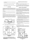
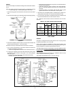
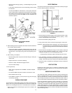
• When communicating with outdoors by means of vertical ducts,
each opening shall have a free area of not less than one square
inch per 4,000 Btu per hour (551 mm
2
/kW) (35 square inches per
gallon of oil consumed per hour) of total input rating of all appliances
in the enclosure.
• If horizontal ducts are used, each opening shall have a free area of
not less than one square inch per 2,000 Btu per hour
(1,101 mm
2
/kW) (70 square inches per gallon of oil consumed per
hour) of total input of all appliances in the enclosure, fig. 5.
APPLIANCE AERATION FROM OUTDOORS (OPTIONAL
FOR CONVENTIONAL BUILDINGS, MANDATORY
FOR TIGHT BUILDINGS)
FIGURE 5
FLUE GAS VENTING
In the absence of any local codes, regulations, or vent pipe or chimney
manufacturer's recommendations, for oil fired equipment, follow the
suggestions below for designing and installing a venting system.
For these water heaters, it is recommended that an adequate chimney
be used for venting the flue gases. Type B, double wall, vent pipe should
be used as the vent connector pipe. However, where no chimney is
available, vent pipe may be used to construct a vent.
Where an existing chimney or vent is to be used, be sure that the chimney
or vent has adequate capacity for the number and sizes of appliances
being vented through it. Inspect the chimney or vent and remove all soot
or other obstructions which will retard free draft.
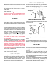
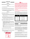
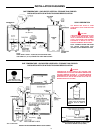
VENT CONNECTOR AND DRAFT REGULATOR
The chimney or vent connector diameter should be the same size as the
heater flue outlet, see Table 4. A minimum rise of 1/4" per foot (21mm/M)
of horizontal connector length must be maintained between the heater
and chimney opening, fig. 6. The connector length should be kept as
short as possible.
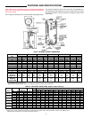
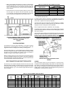
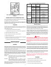
TABLE 4 SUGGESTED VENT CONNECTOR SIZES
Outlet Diameter
Model Number Inches (mm)
GPO 86-199* 6 152.4
GPO 86-245 8 203
GPO 84-315/315A 8 203
GPO 75-385/385A 8 203
GPO 75-455/455A 8 203
GPO 69-700/700A 10 254
* These models are factory supplied with a flue reducer which should
be installed on the top cover.
In venting systems where a continuous or intermittent back (positive)
draft is found to exist, the cause must be determined and corrected. In
some cases, a special vent cap may be required.
If the back draft cannot be corrected by normal methods or if a suitable
draft cannot be obtained, a blower type flue gas exhauster must be
employed to assure venting and correct combustion.
Note: A negative draft must be maintained in the vent piping.
Connections shall not be to a chimney, vent or venting system served by
a power exhauster unless the connection is made on the negative pressure
side of the exhauster.
The barometric draft regulator must be installed in the same room as the
heater, fig. 6. Locate the regulator as close as possible to the heater and
at least 18" (457.2 mm) from a combustible ceiling or wall. A manually
operated damper should not be placed in the chimney connector.
PROPER VENT CONNECTOR INSTALLATION
FIGURE 6
CHIMNEY
The oil-fired water heater must be connected to a chimney built in
accordance with accepted building code practice or listed factory built
type, Table 5. The exit point of the chimney flue gas must be at least 3'
(0.91 M) above the highest point where it passes through the roof of a
building. Also, it must be at least 2' (0.61 M) higher than any portion of a
building within 10' (3.05 M) of the chimney.
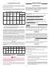
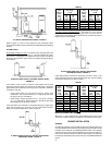
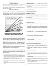
TABLE 5 - USUAL CHIMNEY SIZES FOR UNITS
Oil Equivalent Output Square & Rectangle
Firing Heat Input Heat Stack Round Stack Minimum
Model Rate Rate Rate Dimension Diameter Height
Number (GPH) (LPH) Btuh kW Btuh kW Inches mm Inches mm Feet Metres
GPO 86 -199 1.42 5.38 199,000 58 159,200 47 8 1/2 X 8 1/2 216 x 216 9 228.6 20 6.1
GPO 86 -245 1.75 6.62 245,000 72 196,000 57 8 1/2 X 8 1/2 216 x 216 9 228.6 20 6.1
GPO 84-315 (A) 2.25 8.52 315,000 92 252,000 74 8 1/2 X 13 216 x 330 10 254 30 9.1
GPO 75 -385 (A) 2.75 10.41 385,000 113 308,000 90 8 1/2 X 13 216 x 330 10 254 30 9.1
GPO 75 -455 (A) 3.25 12.30 455,000 133 364,000 107 13 X 13 330 x 330 12 304.8 35 10.7
GPO 69 -700 (A) 5 18.93 700,000 205 560,000 164 13 X 18 330 x 457 14 355.6 40 12.2