9
INSTALLATION OF VENT SYSTEM
(Refer to Figures 3, 4, 5, 7 and 8 as guides).
1. Plan the route of the vent system. Layout the total vent system
to use minimum of vent pipe and elbows. The vent piping
should be vented downward away from the blower per the
required codes. If the vent piping is sloped level or upwards
away from the blower, then adequate means for draining and
disposing of the condensate needs to be made by the installer.
2. Refer to table above for allowable vent lengths. Nonmetallic
vent piping may be used if it has a “Heat Deflection
Temperature” (HDT@66psi) of at least 157 degrees F. Some
typical nonmetallic vent materials meeting this requirement
are PVC to ASTM D2665, CPVC to ASTM D2846, and ABS to
ASTM D2261. The cement used should be as recommended
by the vent pipe manufacturer. The vent terminal provided is
PVC to ASTM D2665 and is a standard 2 inch tee or a 3 inch
45 degree ell. If a material other than PVC is used for venting,
then an equivalent fitting of that material may be substituted if
the screen in the PVC terminal is removed and inserted into
the new fitting. For water heaters installed in locations with
high ambient temperatures (above 100 degrees F), it is
recommended that CPVC or ABS be used.
3. See the instructions on pages 10 through 12 for the proper
method of cutting and cementing the PVC pipe and fittings.
4. The vent piping should be connected to the blower with a
rubber adapter and secured with hose clamps. The adapter
and clamps are provided with the heater.
5. Even though the flue gas temperature leaving the blower is
between 140°F and 175°F, some installations will have water
condense in the vent piping. If this occurs, then adequate
means of draining and disposing of the condensate needs to
be made by the installer.
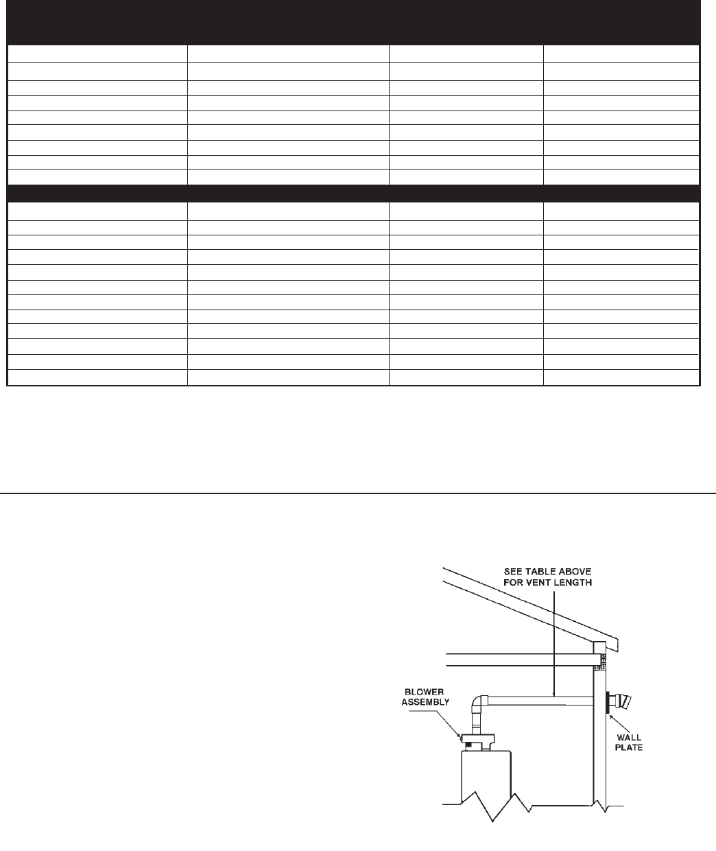
FIGURE 7
The vent pipe may be installed with a slight downward slope
to drain condensate away from the blower. The pipe may
slope 1/4 inch per five feet of pipe but not more than
1 1/2 inches in the total vent length.
The vent pipe should be properly supported and have
supports located no further apart than 5 feet on vertical runs
and 3 feet on horizontal runs. All pipe and fittings should be
joined by the proper procedures discussed on pages 10 and
11 under the heading: VENT PIPE PREPARATION.
TABLE FOR VENT PIPE LENGTH
TWO (2) INCH DIAMETER PIPE
**Number of 90° Elbows **Number of 45° Elbows Minimum Pipe Maximum Pipe
One (1) None 2 Ft. 30 Ft.
One (1) One (1) 1 Ft. 27.5 Ft.
Two (2) None 1 Ft. 25 Ft.
Two (2) One (1) 1 Ft. 22.5 Ft.
Three (3) None 1 Ft. 20 Ft.
Three (3) One (1) 1 Ft. 17.5 Ft.
Four (4) None 1 Ft. 15 Ft.
Four (4) One (1) 1 Ft. 12.5 Ft.
THREE (3) INCH DIAMETER PIPE
** Number of 90° Elbows **Number of 45° Elbows Minimum Pipe Maximum Pipe
One (1) None 2 Ft. 75 Ft.
One (1) One (1) 2 Ft. 72.5 Ft.
Two (2) None 1 Ft. 70 Ft.
Two (2) One (1) 1 Ft. 67.5 Ft.
Three (3) None 1 Ft. 65 Ft.
Three (3) One (1) 1 Ft. 62.5 Ft.
Four (4) None 1 Ft. 60 Ft.
Four (4) One (1) 1 Ft. 57.5 Ft.
***Five (5) None 1 Ft. 55 Ft.
***Five (5) One (1) 1 Ft. 52.5 Ft.
***Six (6) None 1 Ft. 50 Ft.
** One (1) 90° elbow is equal to two (2) 45° elbows.
*** It is not recommended that more than (4) 90° elbows be used, or a combination of three (3) 90° and two (2) 45° elbows, but as long
as the total length is less than in the chart above, the vent system is acceptable.
Note: For the two (2) and three (3) inch diameter vent pipes, one (1) 90° elbow is approximately the same as five (5) feet of the same diameter straight pipe.


