


6
To prevent damage, care must be taken not to apply too much
torque when attaching gas supply pipe to gas valve inlet. The
thermostat inlet has a pad for use with back up wrench.
Apply joint compounds (pipe dope) sparingly and only to the
male threads of pipe joints. Do not apply compound to the first
two threads. Use compounds resistant to the action of liquefied
petroleum gases. Do not use teflon tape on gas valve fittings.
DISCONNECT THE APPLIANCE AND ITS INDIVIDUAL SHUT
OFF VALVE FROM THE GAS SUPPLY PIPING SYSTEM
DURING ANY SUPPLY PRESSURE TESTING EXCEEDING
1/2 PSI (3.5 kPa). GAS SUPPLY LINE MUST BE CAPPED
WHEN DISCONNECTED FROM THE HEATER. FOR TEST
PRESSURES AT 1/2 PSI (3.5 kPa) OR LESS, THE APPLIANCE
NEED NOT BE DISCONNECTED, BUT MUST BE ISOLATED
FROM THE SUPPLY PRESSURE TEST BY CLOSING THE MAIN
MANUAL GAS VALVE.
BEFORE PLACING THE HEATER IN OPERATION, CHECK FOR
GAS LEAKAGE. USE SOAP AND WATER SOLUTION OR OTHER
MATERIAL ACCEPTABLE FOR THIS PURPOSE. DO NOT USE
MATCHES, CANDLES, FLAME OR OTHER SOURCES OF
IGNITION TO LOCATE GAS LEAKS.
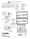
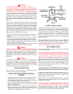
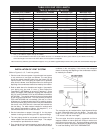
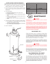
RELIEF VALVE (P)-FIG. 1
A NEW TEMPERATURE AND PRESSURE RELIEF VALVE
COMPLYING WITH THE STANDARD FOR RELIEF VALVES AND
AUTOMATIC GAS SHUT OFF DEVICES FOR HOT WATER
SUPPLY SYSTEMS, ANSI Z21.22 (CURRENT EDITION) MUST
BE INSTALLED IN THE HEATER IN THE MARKED OPENING
PROVIDED. THE VALVE MUST BE OF A SIZE (INPUT RATING)
THAT WILL BE ADEQUATE FOR YOUR SIZE HEATER.
Check the metal tag on the relief valve and compare it to the
heater’s rating plate. The pressure rating of relief valve must not
exceed the working pressure shown on the rating plate of the
heater. In addition the hourly Btu rated temperature steam
discharge capacity of the relief valve shall not be less than the
input rating of the heater.
NO VALVE IS TO BE PLACED BETWEEN
THE RELIEF VALVE AND TANK. DO NOT PLUG THE RELIEF
VALVE.
The drain line connected to this valve must not contain a reducing
coupling or other restriction and must terminate near a suitable
drain to prevent water damage during valve operation. The
discharge line shall be installed in a manner to allow complete
drainage of both the valve and line.
DO NOT THREAD, PLUG
OR CAP THE END OF THE DRAIN LINE.
VENTING
WARNING
NEVER OPERATE THE HEATER UNLESS IT IS VENTED TO
THE OUTDOORS AND HAS ADEQUATE AIR SUPPLY TO AVOID
RISKS OF IMPROPER OPERATION, FIRE, EXPLOSION OR
ASPHYXIATION.
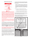
Make sure the flue baffle and flue restrictor ring are properly
aligned and inserted on top of the flue. This can be checked
through the dilution air inlet of the blower.
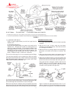
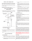
VENT PIPE TERMINATION
NOTE: Before installing power venter determine place of vent
pipe termination. See figure 3 on page 7.
IMPORTANT
The vent system must terminate so that proper clearances are
maintained as cited in local codes or the current edition of the
National Fuel Gas Code, ANSI Z223.1/NFPA 54, 7.3.4e and 7.8a,b,
as follows:
1. The exit terminals of a mechanical vent system shall be not
less than 7 feet above grade when located adjacent to public
walkways. (Figure. 3)
2. A venting system shall terminate at least 3 feet above any
forced air inlet located within 10 feet. (Figure 3)
3. The venting system shall terminate at least 4 feet below, 4
feet horizontally from or, 1 foot above any door, window or
gravity air inlet into any building.
The manufacturer also recommends that the vent termination
should not be installed closer than 3 feet from an inside
corner of an L shaped structure and not be less than 1 foot
above grade.
The vent shall terminate a minimum of 12'' above expected
snowfall level to prevent blockage of vent termination.
4. In cold climates, it is recommended that vent termination not
be mounted directly above or within 3 feet horizontally from an
oil tank vent or gas meter to avoid potential freeze-up from
condensation.
Plan the vent system layout so that proper clearances are
maintained from plumbing and wiring.
Vent pipes serving power vented appliances are classified by
building codes as “vent connectors”. Required clearances from
combustible materials must be provided in accordance with
information in this manual under LOCATION OF HEATER and
VENT TERMINAL INSTALLATIONS, and with the National Fuel
Gas Code and local codes.
IMPORTANT
Plan the layout of the vent system from the vent termination to the
appliance considering all of the 90 degree and 45 degree elbows
plus the number of feet of pipe that would be needed to install
the total vent system. Make sure to include the 90 degree elbow
if required at the blower. Review the tables on page 9 to make
sure that the vent system is within the allowed vent configuration.
Multiple fittings, 90 or 45 degree, installed in close proximity to
each other could result in intermittent lockouts or prevent the
unit from firing. Plan the layout to locate the fittings as far apart
as possible.
CAUTION
Termination of the vent system with a device other than the
supplied type vent terminal could effect system performance
and result in a safety hazard. The 2 inch vent terminal is a tee
and the 3 inch vent terminal is a 45 degree elbow. Both vent
terminals have protective screens.
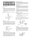
VENT TERMINAL INSTALLATION
1. After the point of termination has been determined, use the
cover plate as a template to mark the hole for the vent pipe to
insert through the wall.
BEWARE OF CONCEALED WIRING
AND PIPING INSIDE OF WALL.
2. If the Vent Terminal is being installed on the outside of a
finished wall, it may be easier to mark both the inside and
outside wall. Align the holes by drilling a hole through the
center of the template from the inside through to the outside.
The template can now be positioned on the outside wall using
the drilled hole as a centering point for the template.