


15
WATER HEATING IGNITION SEQUENCE
(Make sure gas and electric power are connected properly)
1) The ignition control module is powered and monitors the
system, waiting for a call for heat from the thermostat.
2) The thermostat calls for heat by reading a resistance value
within a given range directly proportional to water
temperature.
3) The control Module:
a) Checks the pressure switch for an open circuit.
b) Energizes the blower.
c) Checks the pressure switch for a closed circuit to prove
draft.
d) Sends line voltage to the hot surface igniter with a
20 second warm up period.
e) Opens the gas valve and checks the sensing rod for
flame.
4) The burner heats the water to the desired thermostat setting.
a) The resistance in the thermostat rises to the value
selected by the temperature setting.
b) The control module closes the gas valve and 5 seconds
later, removes power from the blower.
5) Cycle is completed.
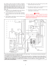
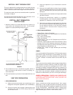
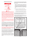
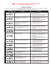
FIGURE 10
CONTROL SEQUENCE - HOT SURFACE DIRECT IGNITION
Pre-purge 5 seconds.
HSI Warm-up 20 seconds.
Ignition Activation Period 4 seconds.
Flame Recognition Period 1 second.
Ignition Trial 4 seconds.
Interpurge 5 seconds.
Post-purge 5 seconds.
Retries 2
Reset from Lockout 1 hr.
Flame Sensing (Nominal)
HSI Off/Run Mode 4.0µV DC
MAINTENANCE
WARNING
DISCONNECT FROM ELECTRICAL SUPPLY BEFORE
SERVICING UNIT.
FOR YOUR SAFETY, WATER HEATER SERVICE SHOULD BE
PERFORMED ONLY BY A QUALIFIED SERVICE TECHNICIAN.
READ THE GENERAL SAFETY INFORMATION SECTION FIRST.
USERS OF THIS APPLIANCE SHOULD BE AWARE THAT GAS
COMPONENTS WEAR OUT OVER A PERIOD OF TIME. THE
GAS CARRYING COMPONENTS OF THIS APPLIANCE SHOULD
BE INSPECTED FOR PROPER OPERATION PERIODICALLY BY
A QUALIFIED SERVICE TECHNICIAN.
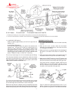
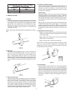
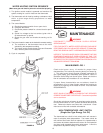
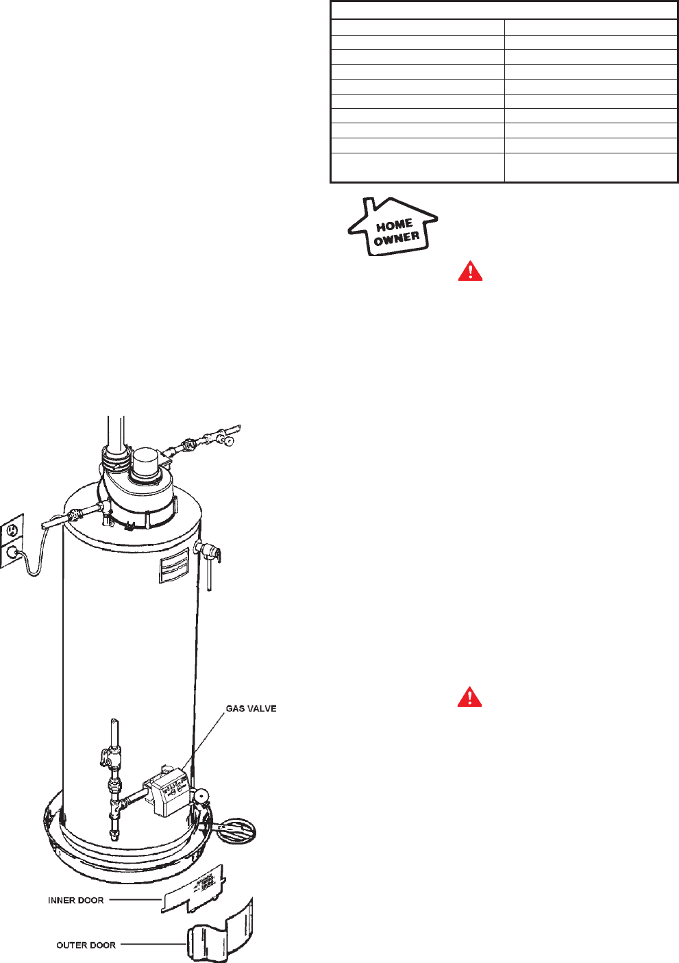
MAIN BURNER -FIG. 1
Check main burner every 12 months for proper flame
characteristics. This is done by removing door(s) on heater, fig.
1. The main burner should provide complete combustion of
gas; ignite rapidly; give reasonably quiet operation; cause no
excessive flame lifting from burner ports. Make sure that the
flow of combustion and ventilation air is not blocked.
If proper flame characteristics are not evident, check for
accumulation of lint or other foreign material that restricts or
blocks the air openings in the heater or burner. Also check AIR
REQUIREMENTS.
WARNING
SOOT BUILD-UP INDICATES A PROBLEM THAT REQUIRES
CORRECTION BEFORE FURTHER USE. Consult with a qualified
service technician.
Should the main burner or burner air openings require cleaning,
turn the blower switch to “OFF” position and allow the burner to
cool. Remove the burner and clean with a soft brush. Clean
main burner orifice with a suitable soft material.
HIGH TEMPERATURE LIMIT SWITCH
(Single-Use Type Energy Cut Off)
The thermostat has a built-in limit switch which will actuate in
case of excessive water temperatures. The heater cannot be
relit until the Gas Control Valve is replaced It is important that a
serviceman be called to determine the reason for limit operation
and thus avoid repeated thermostat replacement. Lower the
temperature adjustment setting on new control.