


7
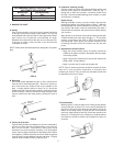
3. A) MASONRY SIDE WALLS
Chisel an opening approximately one half inch larger than the
marked circle.
B) WOODEN SIDE WALLS
Drill a pilot hole approximately one quarter inch outside of the
marked circle. This pilot hole is used as a starting point for a
saws-all or sabre saw blade. Cut around the marked circle
staying approximately one quarter inch outside of the line. (This
will allow the vent pipe to easily slide through the opening. The
resulting gap will be covered up by the vent terminal cover
plates.) Repeat this step on inside wall if necessary.
This unit can vent through 2 or 3 inch nonmetallic pipe and fittings.
The vent pipe installation can be started from either the blower
discharge or the termination wall. Keep in mind the total vent system
(pipe and elbows) when installing the vent system. (SEE VENT
TABLES AND FIGURES ON PAGES 9-10.)
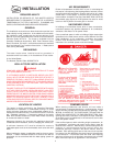
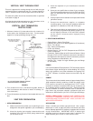
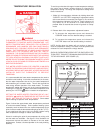
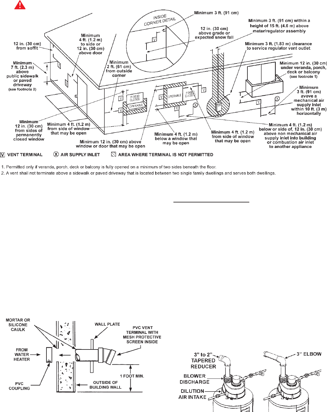
FIGURE 4
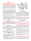
The vent terminal should be kept as close as possible to the outside
wall, but you need to allow at least 1.5 inches of pipe past the wall,
for the wall flange and vent terminal to mount on the pipe.
Before the vent terminal is installed, caulk (not supplied) around the
pipe on the exterior wall and install the wall flange (can be held to the
outside wall by placing some of the caulking on the back of the flange).
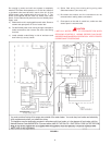
SEQUENCE OF INSTALLATION
1. The Power Vent Models come with the blower assembly
installed.
2. After the unit is set in place, make sure the blower
assembly is still mounted securely. Also make sure there
is no damage to the blower.
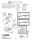
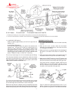
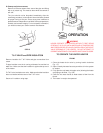
3. Make sure there is no packing material in the discharge of
the blower or the intake of the dilution air restrictor. See
Fig. 5.
4. Make sure that the plastic tubing is still attached from the
air pressure switch to the port on the blower housing.
5. Make sure the ON/OFF switch is in the OFF position and
that the outer harness is connected from the blower control
box to the connector on the bottom side of the gas valve.
If the outer harness is not factory installed, make sure the
ON/OFF switch is in the OFF position and then connect
the outer harness from the blower control box to the
connector on the right side of the gas valve.
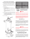
FIGURE 5
Figure 5 shows the optimal placement of the 3” to 2”
reducer; however, the vent can be reduced at any point in
the vent system as long as the 2” vent tables are followed.
FIGURE 3
WARNING
VENT HOOD(S) MAY BE
EXTREMELY HOT DURING
OPERATION