


5
CAUTION
In cold climates provide protection against freeze-up.
THE HEATER SHOULD BE LOCATED IN AN AREA WHERE
LEAKAGE OF THE TANK OR CONNECTIONS WILL NOT RESULT
IN DAMAGE TO THE AREA ADJACENT TO THE HEATER OR TO
LOWER FLOORS OF THE STRUCTURE.
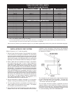
When such locations
cannot be avoided, a suitable drain pan should be installed
under the heater, see fig. 1. The pan should have a minimum
length and width of at least 2 inches greater than the diameter of
the heater and should be piped to an adequate drain. Drain
pans suitable for these heaters are available from your dealer or
State Water Heaters, 500 Lindahl Parkway, Ashland City, TN
37015.
Water heater life depends upon water quality, water pressure
and the environment in which the water heater is installed. Water
heaters are sometimes installed in locations where leakage
may result in property damage, even with the use of a drain pan
piped to a drain. However, unanticipated damage can be reduced
or prevented by a leak detector or water shut-off device used in
conjunction with a piped drain pan. These devices are available
from some plumbing supply wholesalers and retailers, and
detect and react to leakage in various ways:
• Sensors mounted in the drain pan that trigger an alarm or turn
off the incoming water to the water heater when leakage is
detected.
• Sensors mounted in the drain pan that turn off the water supply
to the entire home when water is detected in the drain pan.
• Water supply shut-off devices that activate based on the water
pressure differential between the cold water and hot water
pipes connected to the water heater.
• Devices that will turn off the gas supply to a gas water heater
while at the same time shutting off its water supply.
WARNING
DO NOT INSTALL THIS WATER HEATER DIRECTLY ON A
CARPETED FLOOR. A FIRE HAZARD MAY RESULT.
Instead the
water heater must be placed on a metal or wood panel extending
beyond the full width and depth by at least 3 inches (76.2mm) in
any direction. If the heater is installed in a carpeted alcove or
closet, the entire floor shall be covered by the panel. Also, see
DRAINING.
WARNING
For California installation this water heater must be braced,
anchored, or strapped to avoid falling or moving during
an earthquake. See instructions for correct installation
procedures. Instructions may be obtained from your local dealer,
wholesaler, public utilities or California’s Office of the State
Architect, 400 P Street, Sacramento, CA 95814.
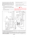
WATER CONNECTIONS
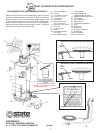
Refer to figure 1 for typical installation. A suitable pipe thread
sealant must be used to prevent leakage.
WATER (POTABLE) HEATING AND SPACE
HEATING
1. All piping components connected to this unit for space heating
applications shall be suitable for use with potable water.
2. Toxic chemicals, such as those used for boiler treatment,
shall NEVER be introduced into this system.
3. This unit may NEVER be connected to any existing heating
system or component(s) previously used with a non-potable
water heating appliance.
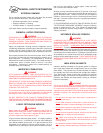
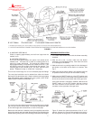
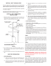
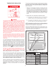
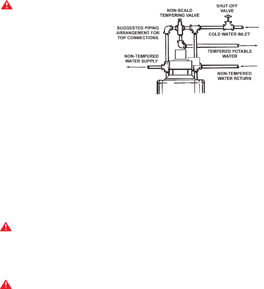
4. When the system requires water for space heating at
temperatures higher than required for domestic water
purposes, a tempering valve must be installed. Please refer
to Figure 2 for suggested piping arrangement.
FIGURE 2
CLOSED WATER SYSTEM
A closed system will exist if a back-flow preventer (check valve),
or similar device is installed in the cold water line between the
water heater and the street main (or well). Excessive pressure
may develop due to the thermal expansion of heated water
causing premature tank failure or intermittent relief valve
operation. This type of failure is not covered by the limited
warranty. An expansion tank may be necessary in the cold water
supply to alleviate this situation, see fig. 1. Contact the local
plumbing authority.
If the temperature and pressure relief valve on the appliance
discharges periodically, this may be due to thermal expansion
in a closed water supply system. Contact the water supplier or
local plumbing inspector on how to correct the situation.
Do not
plug the temperature and pressure relief valve.
GAS CONNECTIONS
The minimum gas supply pressure is 4.5" W.C for natural gas
(11.0" W.C. for propane).
THE HEATER IS NOT INTENDED FOR OPERATION AT HIGHER
THAN 14.0'' WATER COLUMN SUPPLY PRESSURE. EXPOSURE
TO HIGHER GAS SUPPLY PRESSURE MAY CAUSE DAMAGE
TO THE CONTROL WHICH COULD RESULT IN FIRE OR
EXPLOSION.
If overpressure has occurred such as through
improper testing of gas lines or emergency malfunction of the
supply system, the control must be checked for safe operation.
Make sure that the outside vents on the supply regulators and
the safety vent valves are protected against blockage. These
are parts of the gas supply system not the heater. Vent blockage
may occur during ice storms.
IT IS IMPORTANT TO GUARD AGAINST CONTROL FOULING
FROM CONTAMINANTS IN THE GAS WAYS. SUCH FOULING
MAY CAUSE IMPROPER OPERATION, FIRE OR EXPLOSION.
All piping must comply with local codes and ordinances or with
the National Fuel Gas Code (ANSI Z223.1/ NFPA-54) whichever
applies. Copper and brass tubing and fittings (except tin lined
copper tubing) shall not be used.
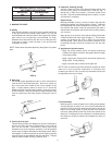
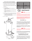
REFER TO FIG. 1 FOR CONNECTION DETAILS. BEFORE
ATTACHING THE GAS LINE BE SURE THAT ALL GAS PIPE IS
CLEAN ON THE INSIDE.
TO TRAP ANY DIRT OR FOREIGN MATERIAL IN THE GAS
SUPPLY LINE, A DIRT LEG (SOMETIMES CALLED DRIP LEG)
MUST BE INCORPORATED IN THE PIPING, FIG. 1.
The dirt leg
must be readily accessible. Install in accordance with
recommendations of serving gas supplier. Refer to the current
edition of National Fuel Gas Code, ANSI Z223.1/NFPA.