7
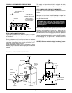
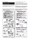
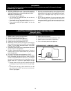
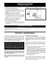
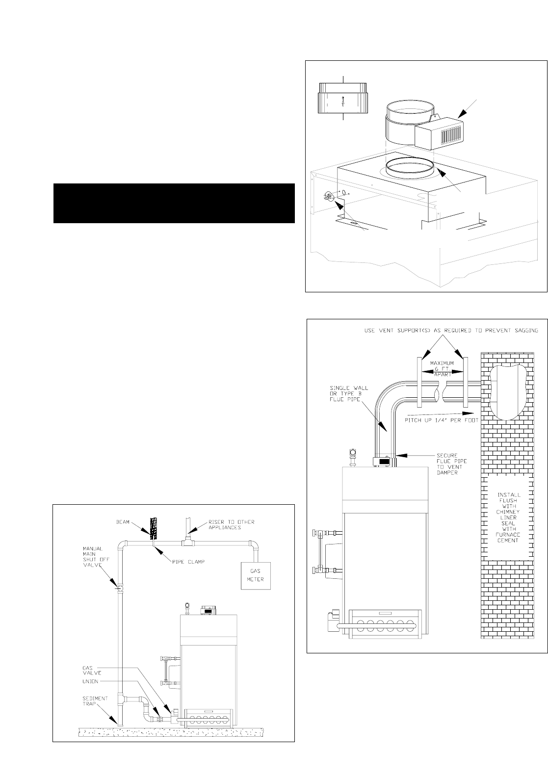
FIGURE 2.5: ATTACHING VENT DAMPER TO DRAFT
DIVERTER & FLUE PIPE
FLOW DIRECTION
ARROW POINTS UP
(REAR VIEW)
MAKE SURE MOTOR IS
LOCATED ON FRONT SIDE
CLOSED OPEN
FLOW DIRECTION
MOUNT VENT DAMPER
OVER DRAFT DIVERTER
INSTALL SWITCH IN
OPENING
ON DRAFT DIVERTER
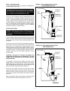
ADDITIONAL CHIMNEY REQUIREMENTS
Chimney condition is of paramount importance for a safe and
efficient boiler installation. All installations must include a
chimney inspection by a qualified individual or agency. Chim-
ney construction materials must be compatible with the fuel
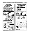
being used (See Figure 2.5A).
Particular attention should be paid on all oil-to-gas conver-
sions. Soot may have accumulated in chimney and/or
degraded chimney liner. Most utilities require complete chim-
ney cleaning. Others may require installation of new liner,
spill switches or other chimney upgrades. Check with local
utility for required safety precautions.
STEP 5: INSTALLING/TESTING GAS PIPING
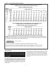
Connect the gas piping from the meter to the boiler using a
pipe size which will result in a pressure drop of less than 0.3"
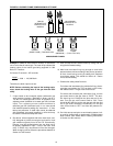
W.C. for natural gas or 0.5" W.C. for propane. See Figure 2.7
for the appropriate gas pipe sizing and example.
Good piping practices should be followed at all times. See
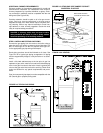
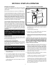
Figure 2.6 for a typical gas piping arrangement. All piping
must be supported by hangers, not by the boiler or its acces-
sories.
Install a full-sized sediment trap at the low point in gas line
upstream of gas valve. Install a non-restrictive lubricated plug
valve in the gas line close to the boiler. Install a ground joint
union at the gas valve inlet to allow for servicing. Check local
codes and utilities for any special requirements and proce-
dures.
Pipe joint compound (pipe dope) must be compatible with the
fuel (natural gas or propane) being used.
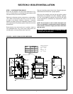
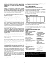
FIGURE 2.6: TYPICAL GAS PIPING
DANGER: A chimney which does not meet modern
safety standards will result in a fire or deadly carbon
monoxide poisoning of the building residents.
FIGURE 2.5A: VENTING


