


5
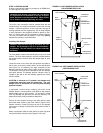
STEP 2: INSTALLING STEAM PIPING
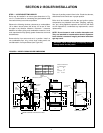
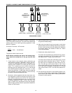
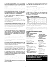
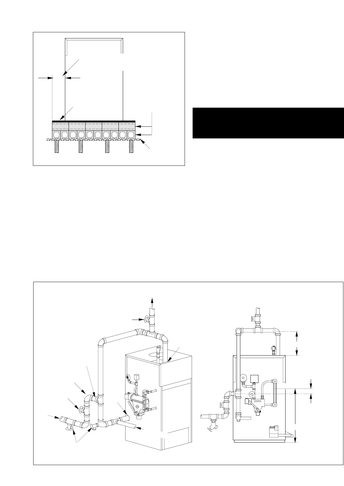
Typical piping connections are shown in Figure 2.3. All exter-
nal piping must be supported by hangers, not by the boiler or
its accessories.
Supply outlet must run full size from the boiler to a header at
least 24" above top of boiler. Condensate return piping
should be connected to boiler through a "Hartford Loop."
Install gate valves in supply and return.
Proper steam piping practices must be followed at all times.
Maintain proper clearances between piping and combustible
material.
The supply and return lines should be equipped with drain
cocks to drain sediment and sludge from lowest points of
boiler.
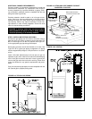
STEP 3: INSTALLING HYDRONIC COMPONENTS
A low-water cutoff must be installed to protect the unit from
dry fire.
Screw extension nipple into 3/4" tapping on top of the
absorption unit and install relief valve into top of nipple with
the spindle in the vertical position (i.e., with the valve dis-
charge in the horizontal).
Most localities require the discharge piping to terminate with-
in 6" of the floor. Check local code requirements if in doubt.
Discharge piping must be of same size or larger than the
relief valve outlet and should be run as short and straight as
possible. Elbows in the discharge piping should be placed as
close to the valve as possible. If valve discharge is to be
drained away, the discharge piping must not be hard-piped to
the drain piping (i.e., an open funnel or similar arrangement
must be used).
CAUTION: Piping must be installed from the relief valve
discharge so there will be no danger of scalding person-
nel.
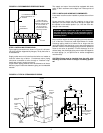
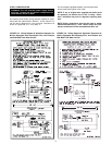
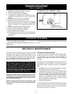
FIGURE 2.2: RECOMMENDED FIREPROOF BASE
4" HOLLOW CLAY
TILE (TWO COURSES)
OPENINGS THRU BLOCKS
IN TOP COURSE TO
BE AT 90° ANGLE
TO OPENINGS THRU
BOTTOM COURSE
22 GAUGE
SHEETMETAL
FLOOR
6"
6" OVERHANG OF BLOCKS
AND SHEETMETAL ALL
AROUND
C/L OF HARTFORD
LOOP TO BE 2"
BELOW WATER
LINE
12" MIN.
SUPPLY
TAPPING
3" NPT
GATE
VALVE
DRAIN
COCKS
GATE VALVE
RETURN
TAPPING
2" NPT
HARTFORD
LOOP
MUST BE CLOSE
NIPPLE
STEAM
SUPPLY
RETURN
WATER LINE
23 1/4"
COLD WATER FILL
FIGURE 2.3: TYPICAL STEAM BOILER PIPING
WARNING: Never install any type of valve between
the boiler and the relief valve or an explosion causing
extensive property damage, severe personal injury or
death may occur!