12
Example: A GB200-4L boiler takes 5 minutes, 27 seconds to
use 10 cubic feet of natural gas. The local utility indicated the
heating value of the natural gas being supplied is 1000
Btu/cu ft. Therefore:
5 minutes, 27 seconds = 327 seconds.
36,000
x 1000 = 110,000 Btu/hr
327
Therefore, the boiler input is correct.
NOTE: Before calculating the input of the heating equip-
ment, obtain the heating value of the gas from the local
utility.
7. If input needs to be corrected, adjust combination gas
valve pressure regulator. (Regulator is factory set at 3-
1/2" W.C. for natural gas and 10" W.C. for propane.) Turn
adjusting screw clockwise to increase gas flow (increase
input). Turn adjusting screw counterclockwise to
decrease gas flow (decrease input). In no case should
final manifold pressure setting vary more than + .3" from
factory-set pressures. If rated input cannot be obtained
with adjustment, gas supply pressure or orifice size may
be cause. Consult local utility and Smith.
8. Gas burner orifices supplied with boiler have been care-
fully designed to provide correct gas input rate for most
gas conditions typically found in the U.S. Occasionally,
however, local gas characteristics may not allow unit to
be properly adjusted for input. If this is the case, local
utility or Smith may recommend orifices be changed.
When changing orifices follow the procedures detailed in
Section 4 of this manual.
9. Start and stop burners several times by raising and low-
ering the thermostat setting.
10. After boiler has been firing long enough to raise boiler
pressure above minimum setting of the primary pressure-
tol limit, check limit by turning its setting from maximum
to minimum setting. This should turn boiler off. Return
limit to desired setting.
11. Check boiler safety shutoff controls.
For boilers with intermittent pilot, with boiler firing, discon-
nect wire connected to the "PV" terminal on the Honey-
well S8600 control. The gas valve should close.
For boilers with constant pilot, with boiler firing, turn the
gas control knob on the gas valve to “PILOT”. The burn-
ers should go out. Extinguish the pilot and wait 3 min-
utes. Turn the gas valve control knob to “ON”. There
should be NO gas flow to the main burners with the pilot
out! If gas flow is detected, immediately turn the gas
valve control knob to “OFF” and have the problem cor-
rected.
12. On initial start-up and prior to each heating season, boil-
er must be cleaned with a commercially available steam
boiler cleaner (see "Steam Boiler Cleaning Instructions"
in Section 4 of this manual).
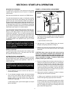
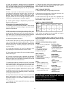
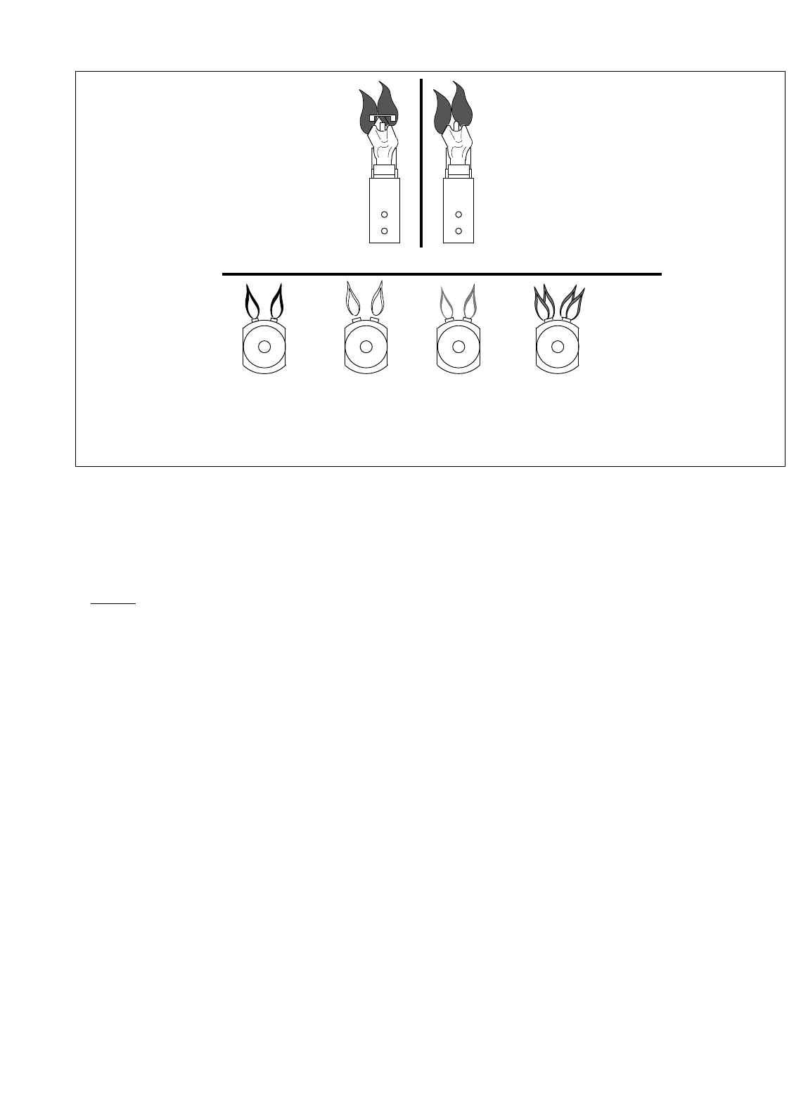
FIGURE 3.2: BURNER FLAME COMPARISON/PILOT FLAME
YELLOW
FLAME
(TOO LITTLE AIR)
YELLOW
TIPPING
(MARGINAL)
LIFTING
(TOO MUCH AIR)
NORMAL
(HARD FLAME)
NORMAL PILOT FLAME
MAIN BURNER FLAMES
Q314A/Q309A
CONSTANT PILOT
MODELS
Q3451B
INTERMITTENT
IGNITION PILOT
MODELS


