


6. Selection and setting of equipment
6-1. Sensing DC mode
1. selection of bar length
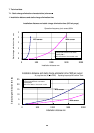
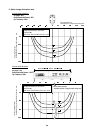
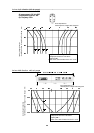
Select the length applicable to work size base on [2. static charge elimination area of 7-1.
static charge elimination characteristics (reference)]
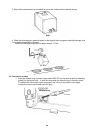
2. Installation of ionizer body
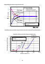
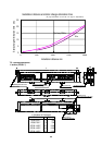
Installation of ionizer body: Install within 200mm to 2000mm from the target’s static charge
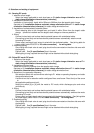
See data of [1. Installation distance and static charge elimination time of 7-1. static charge
elimination characteristics (reference)] for static charge elimination time.
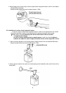
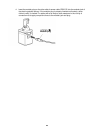
3. Installation of surface electric potential sensor
Direct detecting hole to the charged face, and install it within 50mm from the target’s static
charge. (should be installed near the target’s static charge as close as possible.
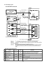
4. Wiring
Connect ionizer body and surface electric potential sensor with a dedicated cable.
Connecting ionizer body and surface electric potential sensor automatically sets the mode
to sensing DC mode.
Power supply and each input/ output is wired with the dedicated cables. See [wiring table for
power supply cable IZS30-CP of 4-3 cable connection] for wiring table.
5. Pneumatic piping
Since fitting with check valve is used, plug should not be connected on the other side even with
single piping.
Pipe 4 tube. See [3. specifications] for air flow rate.
When piping is long, required flow rate might not be obtained without both-side piping.
6-2. Pulsed DC mode/ DC mode
1. Selection of bar length
Select the length applicable to work size base on [2. static charge elimination area of 7-1.
static charge elimination characteristics (reference)]
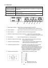
2. Installation of ionizer body
Install within 50mm to 2000mm from the target’s static charge
See data of [1. Installation distance and static charge elimination time of 7-1. static charge
elimination characteristics (reference)] for static charge elimination time.
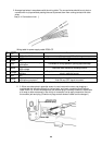
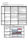
3. Selection of ion generation frequency
Set selection switch with a screw driver referring to P1 data on operating frequency and static
charge elimination time .
A screw driver slot for selection switch configures like a small arrow. Direct the tip of the arrow
to
the applicable position and set it.
Setting the switch [8] or [9] shift the mode to DC mode, which discharges plus and minus
continuously.
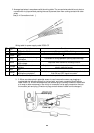
4. Wiring
Connect ionizer body and surface electric potential sensor with a dedicated cable.
Connecting ionizer body and surface electric potential sensor automatically switches the mode
to sensing DC mode.
Power supply and each input/ output is connected with the dedicated cables. See [wiring table
for power supply cable IZS30-CP of 4-3 cable connection] for wiring table.
5. Pneumatic piping
Since fitting with check valve is used, plug should not be connected on the other side even with
single piping.
Pipe 4 tube. See [3. specifications] for air flow rate.
When piping is long, required flow rate might not be obtained without both-side piping.