


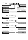
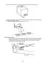
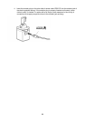
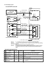
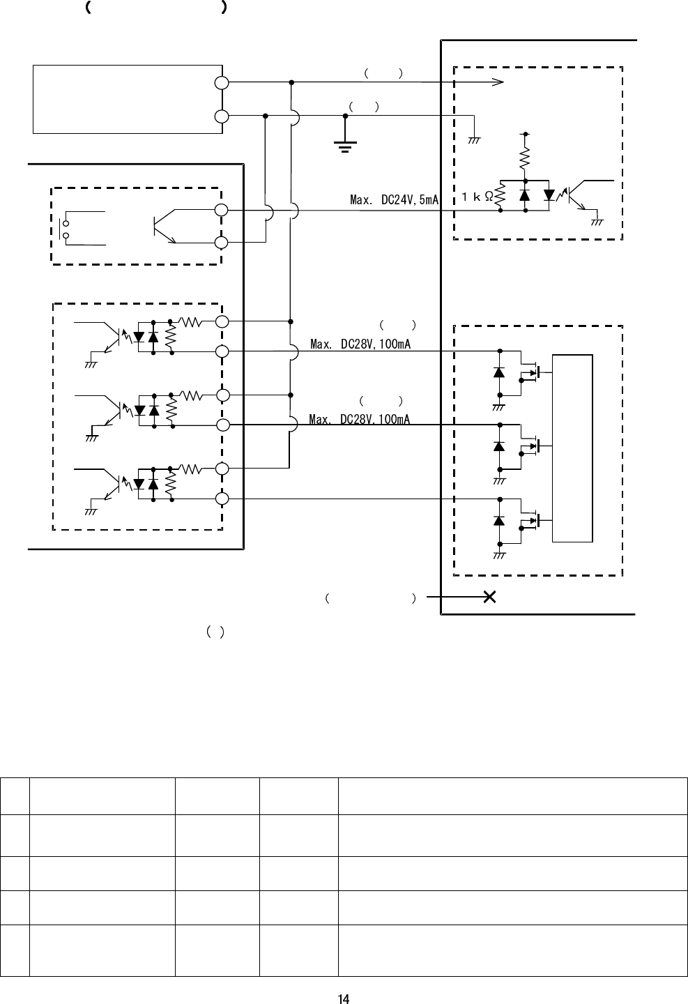
4-4. Connection circuit
Ionizer POWER connector
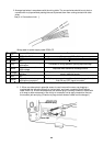
[Note 1] indicates the coating color for lead wire of dedicated cable
[Note 2] Connect [4. Stop signal of static charge elimination] to GND when starting
the ionizer operation.
When the terminal is open, the operation will stop.
[Note 3] [6. signal for abnormal sensor] and [8. signal for static charge elimination
completion] functions only when the surface electric potential sensor is
used.
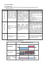
Input and output operation list
Name
Lead wire
color
Signal Operation
4
Stop signal of
charge elimination
Gray Input
Connect 4 terminal to GND during operation
Discharge stops when terminal 4 is open.
5
Signal for abnormal
High voltage
White Output
Tr1 in ionizer is ON when abnormal signal is being
sent.
6
Signal for abnormal
sensing
Orange Output
Tf2 in ionizer is ON is conducted when abnormal
signal is being sent.
8
Signal for static
charge elimination
completion
Yellow Output
Tr 3 in ionizer is ON when static charge elimination
is completed.
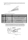
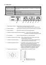
1.DC+24V Brown
4.
Stop signal
of
charge elimination(Gray)
2.GND Blue
3.7 NC Green and red
Ionizer
INPUT
5.
Signal for abnormal
high voltage White
6.
Signal for abnormal
sensing Orange
8.
Signal fo
r static
elimination completion
Max. DC28V,100mA
ౝ
ૡ
࿁
ऍ
OUTPUT
24V
6.8k
Power supply
DC21.6 to 26.
4V
ᯛ
ᯛᯛ
ᯛ
GND
or
OUTPUT
INPUT
PLC
F.G
Internal circuit