


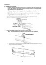
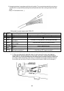
2. Arrange lead wires in accordance with the wiring table. The unused wires should be cut short or
covered with vinyl tape without pealing the coat to prevent them from coming contact with other
wires.
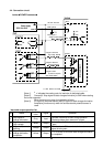
See [4-4. Connection circuit ].
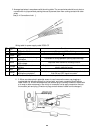
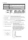
Wiring table for power supply cable IZS30-CP
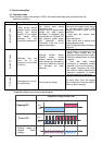
Note No. 6 and 8 only function when a surface electric potential sensor is used.
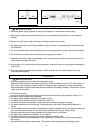
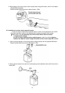
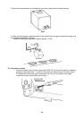
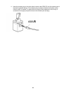
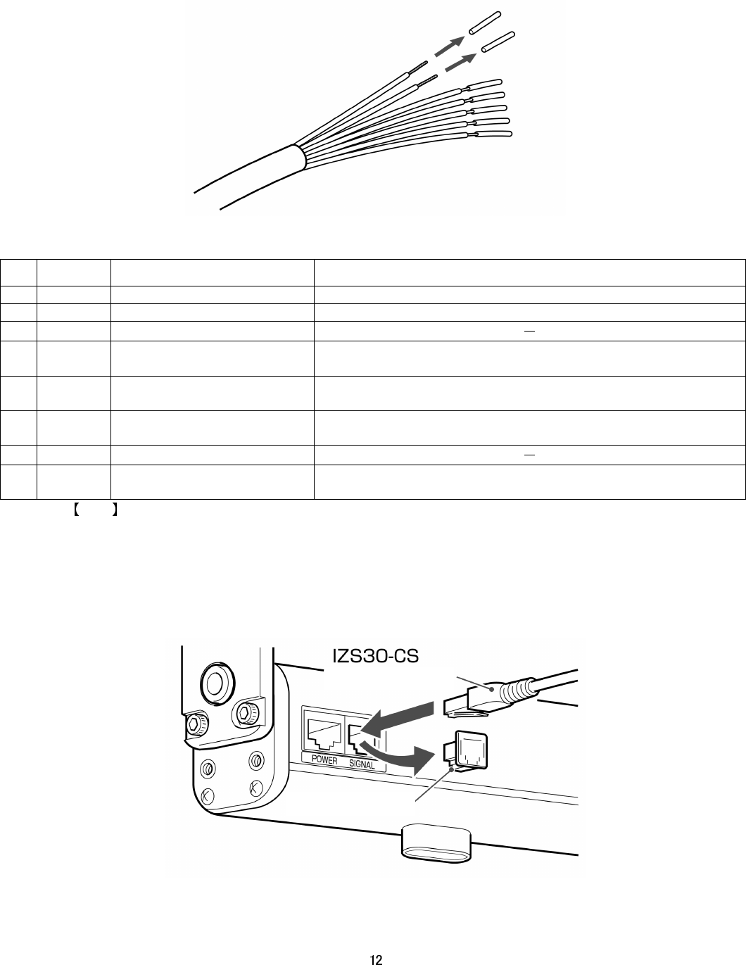
3. 3. When a surface electric potential sensor is used, remove the cover cap plugging a
modular jack for indicating [signal] on ionizer body, and insert a modular plug of sensor
cable IZS30-CS. A lever will snap when the modular plug is correctly locked Fix cables with
a tie wrap or other measures in the vicinity of connection not to apply compulsive force to
the modular jack and plug. (Direction of plugs on both sides of cable can be changed.)
Pin
Lead wire
color
Description Function
1 Brown DC21.6 to 26.4V Power supply DC + 24 V
2 Blue GND Power supply 0V. Be sure to apply class D grounding.
3
Green
NC
4
Gray
Stop signal of static charge
elimination
Connected 0V during operation. Opening stops discharge.
5
White
Signal for abnormal
High voltage
Outputted when abnormal discharge occurs.
6
Orange
Signal for abnormal
sensing
Outputted when abnormal operation occurs on the surface
electric potential sensor.
7
Red
NC
8
Yellow
Signal for static charge
elimination completion
Notify the progress and completion of static charge elimination
with ON and OFF signal to outside.
Modular plug
Cover cap