


Si4421
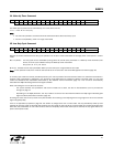
14. Wake-Up Timer Command
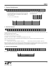
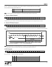
Bit 15 14 13 12 11 10 9 8 7 6 5 4 3 2 1 0 POR
1 1 1 r4 r3 r2 r1 r0 m7 m6 m5 m4 m3 m2 m1 m0 E196h
The wake-up time period can be calculated by (m7 to m0) and (r4 to r0):
T
wake-up
= 1.03 · M · 2
R
+ 0.5 [ms]
Note:
For continual operation, the ew bit should be cleared and set at the end of every cycle.
For future compatibility, use R in a range of 0 and 29.
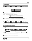
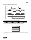
15. Low Duty-Cycle Command
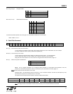
Bit 15 14 13 12 11 10 9 8 7 6 5 4 3 2 1 0 POR
1 1 0 0 1 0 0 0 d6 d5 d4 d3 d2 d1 d0 en C80Eh
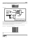
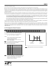
With this command, autonomous low duty-cycle operation can be set in order to decrease the average power consumption in receive
mode.
Bits 7-1 (d6-d0): The duty-cycle can be calculated by using (d6 to d0) and M. (M is parameter in a Wake-Up Timer Command, see
above). The time cycle is determined by the Wake-Up Timer Command.
duty-cycle= (D · 2 +1) / M · 100%
Bit 0 (en): Enables the low duty-cycle Mode. Wake-up timer interrupt is not generated in this mode.
Note: In this operation mode, bit er must be cleared and bit ew must be set in the Power Management Command (page 15).
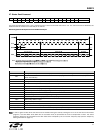
I
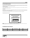
n low duty-cycle mode the receiver periodically wakes up for a short period of time and checks if there is a valid FSK transmission in
progress. FSK transmission is detected in the frequency range determined by Frequency Setting Command (page 17) plus and
mi
nus the baseband filter bandwidth determined by the Receiver Control Command (page 17). This on-time is automatically
extended while DQD indicates good received signal condition.
When calculating the on-time take into account:
- the crystal oscillator, the synthesizer and the PLL needs time to start, see the AC Characteristics (Turn-on/Turnaround
timings) on page 11
- depending on
the DQD parameter, the chip needs to receive a few valid data bits before the DQD signal indicates good
signal condition (Data Filter Command, page 19)
Choosing too short on-time can prevent the crystal oscillator from starting or the DQD signal will not go high even when the received
signal has good quality.
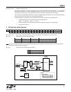
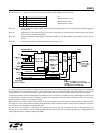
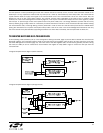
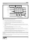
There is an application proposal on page 26. The Si4421 is configured to work in FIFO mode. The chip periodically wakes up and
switches to receiving mode. If valid FSK data received, the chip sends an interrupt to the microcontroller and continues filling the RX
FIFO. After the transmission is over and the FIFO is read out completely and all other interrupts are cleared, the chip goes back to low
power consumption mode.
25