


Si4421
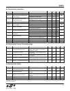
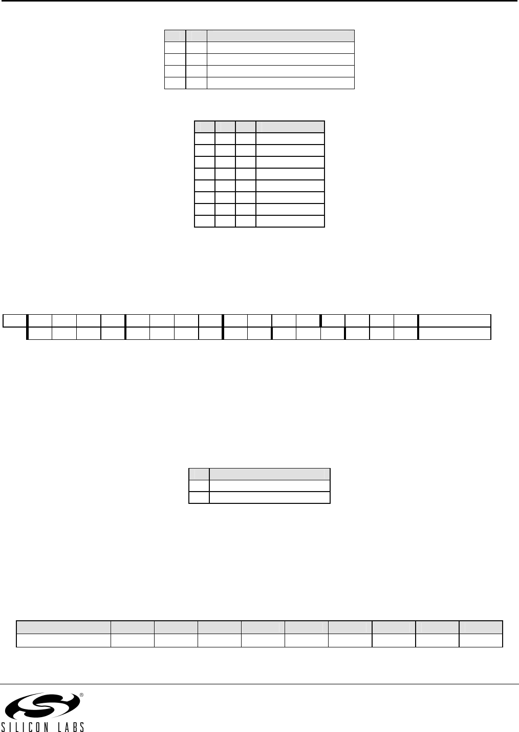
Bits 4-3 (g1 to g0): LNA gain select:
g1 g0 Gain relative to maximum [dB]
0 0 0
0 1 -6
1 0 -14
1 1 -20
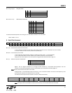
Bits 2-0 (r2 to r0): RSSI detector threshold:
r2 r1 r0
RSSI
setth
0 0 0 -103
0 0 1 -97
0 1 0 -91
0 1 1 -85
1 0 0 -79
1 0 1 -73
1 1 0 Reserved
1 1 1 Reserved
The RSSI threshold depends on the LNA gain, the real RSSI threshold can be calculated:
RSSI
th
=RSSI
setth
+G
LNA
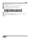
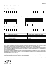
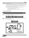
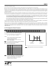
6. Data Filter Command
Bit 15 14 13 12 11 10 9 8 7 6 5 4 3 2 1 0 POR
1 1 0 0 0 0 1 0 al ml 1 s 1 f2 f1 f0 C22Ch
Bit 7 (al): Clock recovery (CR) auto lock control
1: auto mode: the CR starts in fast mode, after locking it switches to slow mode. Bit 6 (ml) has no effect.
0: manual mode, the clock recovery mode is set by Bit 6 (ml)
Bit 6 (ml): Clock recovery lock control
1: fast mode, fast attack and fast release (4 to 8-bit preamble (1010...) is recommended)
0: slow mode, slow attack and slow release (12 to 16-bit preamble is recommended)
Using the slow mode requires more accurate bit timing (see Data Rate Command, page 17).
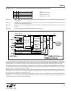
Bit 4 (s):
Select the type of the data filter:
s Filter Type
0 Digital filter
1 Analog RC filter
Digital: This is a digital realization of an analog RC filter followed by a comparator with hysteresis. The time
constant is automatically adjusted to the bit rate defined by the Data Rate Command (page 17).
Note: Bit rate cannot exceed 115 kpbs in this mode.
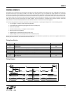
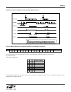
Analog RC filter: The demodulator output is fed to pin 7 over a 10 kOhm resistor. The filter cut-off frequency is set
by the external capacitor connected to this pin and VSS.
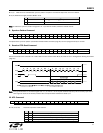
The table shows the optimal filter capacitor values for different data rates
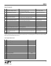
Data Rate [kbps] 1.2 2.4 4.8 9.6 19.2 38.4 57.6 115.2 256
Filter Capacitor Value 12 nF 8.2 nF 6.8 nF 3.3 nF 1.5 nF 680 pF 270 pF 150 pF 100 pF
Note: If analog RC filter is selected the internal clock recovery circuit and the FIFO cannot be used.
19