42
7. INSTALLATION INSTRUCTIONS
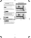
7-1. Installation Site Selection
7-1-1. Indoor Unit
WARNING
To prevent abnormal heat
generation and the possibility
of fire, do not place obsta-
cles, enclosures and grilles
in front of or surrounding the
air conditioner in a way that
may block air flow.
Max. Allowable Tubing Limit of Tubing Limit of Elevation Required Amount of
Length at Shipment Length (L) Difference (H) Additional Refrigerant Model
(ft.) (ft.) (ft.) (oz./ft.)
*
25 50 23 a) 0.16 9,000 BTU
25 65 23 b) 0.27 12,000/18,000 BTU
*
If total tubing length becomes a) 25 to 50 ft. (max.), b) 25 to 65 ft. (max.) charge additional refrigerant (R22) by a) 0.16 oz./ft., b) 0.27 oz./ft.
No additional compressor oil is necessary.
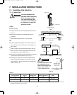
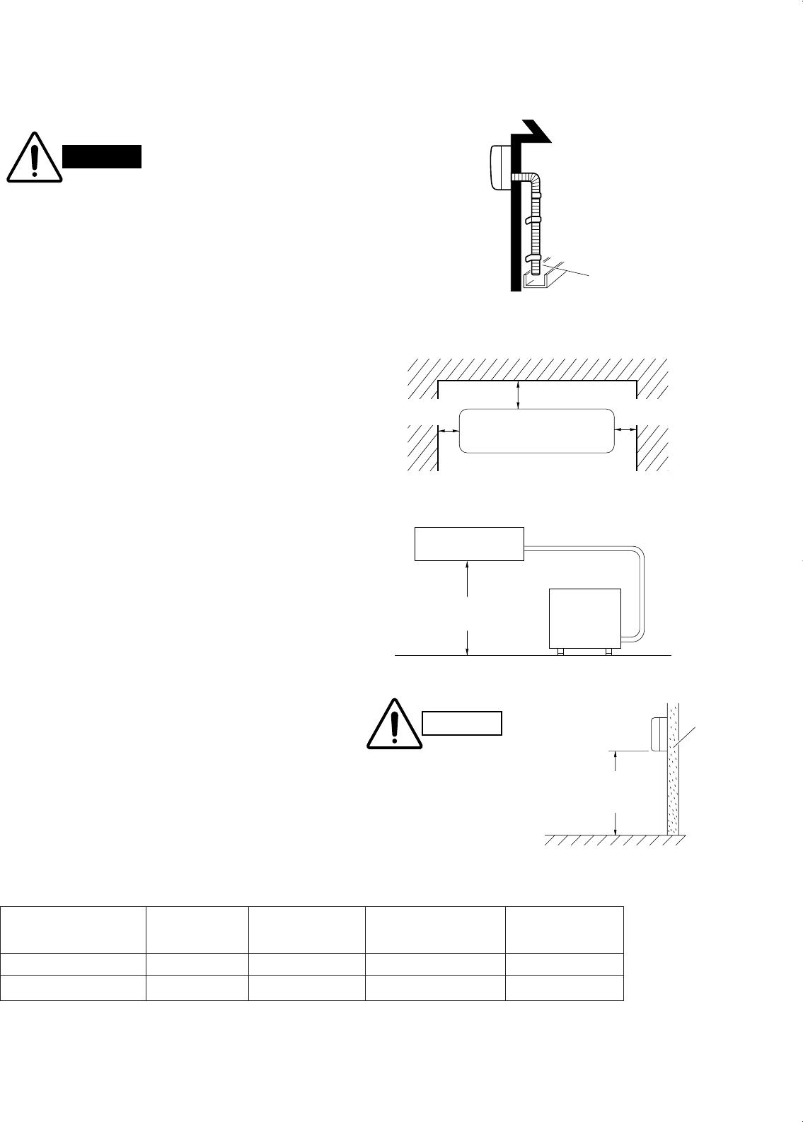
Drain hose
Indoor unit
Outside drainage
Fig. 1
*6" (15 cm) min.
Front View
2" (5 cm) min.
*6" (15 cm) min.
*KS1852 only
2" (5 cm) min.
*6" (15 cm) min.
2" (5 cm) min.
Fig. 2
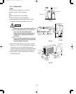
INDOOR
UNIT
Tubing length (L)
OUTDOOR
UNIT
Elevation
difference (H)
Fig. 3a
Indoor unit
Floor level
Wall
Minimum height
from floor level
5 ft. (1.5 m)
Fig. 3b
For stable operation of the
air conditioner, do not
install wall-mounted type
indoor units under 5 ft.
(1.5 m) from floor level.
CAUTION
Table 1
AVOID:
●
direct sunlight.
●
nearby heat sources that may affect performance of
the unit.
●
areas where leakage of flammable gas may be
expected.
●
places where large amounts of oil mist exist.
DO:
●
select an appropriate position from which every cor-
ner of the room can be uniformly cooled. (High on a
wall is best.)
●
select a location that will hold the weight of the unit.
●
select a location where tubing and drain hose have
the shortest run to the outside. (Fig. 1)
●
allow room for operation and maintenance as well as
unrestricted air flow around the unit. (Fig. 2)
●
install the unit within the maximum elevation differ-
ence (H) above the outdoor unit and within a total
tubing length (L) from the outdoor unit as detailed in
Table 1 and Fig. 3a.
*
KHS1852 only
000-111 SM (18-68) 00.3.17 11:49 AM y[W 42


