


SECTION 1: INTRODUCTION
3 of 62
-OR-
CORAYVAC
®
systems designed shall have
recommended radiant pipe length and 1.2 - 1.5 feet
per flow unit of tailpipe length. See the CORAYVAC
®
Design Manual (P/N 127500NA) for minimum and
recommended radiant pipe length.
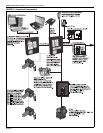
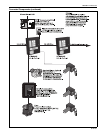
1.5 Example Site Layout
Page 15, Figure 6 is an example layout for a building
where ROBERTS GORDON
®
ULTRAVAC™ will be
used to control the infrared heating systems shown.
The layout consists of three zones of ROBERTS
GORDON
®
ULTRAVAC™.
1.6 Check Installation Materials
1.6.1 Switchable Loads
The controller relays are rated for switching loads no
greater than 3 A. The total added current load for all
8 relays must not exceed 25 A.
1.6.2 Control Wiring
Shielded cable (four twisted pairs of stranded 24
AWG minimum wire) is required for use with
indoor sensors.
Shielded cable (one twisted pair of stranded 22
AWG minimum wire) is required for the outdoor
air sensor, VFD signal wiring, pressure switch
and wiring from controller
#
1 to the PC.
Shielded cable (one twisted pair of stranded 22
AWG minimum wire) is required for RS-485
communications between controllers.
1.6.3 Control Board and Sensor Power
The power supply for all sensors is from the “+32 V”
terminal to be found on the board of the controller.
Power for the control board is 24 V provided by the
relay board.
1.6 .4 Programming Details
Every controller is pre-programmed for one pump
and up to three heating zones. Use a site
layout drawing to identify the heating zones.
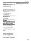
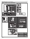
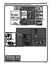
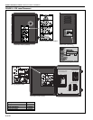
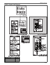
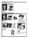
1.7 Safety Labels and Their Placement
Product safety signs or labels should be replaced by
the product user when they are no longer legible.
Please contact Roberts-Gordon LLC or your ROB-
ERTS GORDON
®
independent distributor to obtain
replacement signs or labels. See Page 4, Figure 1
through Page 7, Figure 4.