


ROBERTS GORDON
®
ULTRAVAC™ CONTROLLER INSTALLATION MANUAL
60 of 62
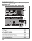
10.5 Replacement Parts Instructions
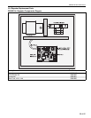
10.5.1 Plug-In Relay
To replace the plug-in relay, turn off 120 V power to
the relay board. Turn off the 24 V power switch on the
relay board. Locate the malfunctioning relay and pull
the relay from its socket.
Fit a new relay in the socket. Return 120 V power to
the relay board and turn on the 24 V power switch on
the relay board. Press the reset button on the control
board and close the doors.
10.5.2 Control Board Power LED
The LED is linked to the 24 Vac input which supplies
the control board with power. If the LED is not lit,
there is no power to the board. If this is the case,
check the 120 V power wiring to the relay board, the
24 Vac power wiring from the relay board to the con-
trol board and the 24 V power 1 A fuse.
10.5.3 10080122 Eprom Chip
The Eprom is where the controller's program
(not settings) is stored. To take out the Eprom.
The following steps must be taken:
Turn off the power to the control board by turning off
the 24 V power switch on the relay board.
Locate the Eprom and with a small terminal scre
w
driver placed underneath the device, pry the Eprom
out of the socket.
To fit a new Eprom, look for the notch on one end of
the Eprom.There is a notch on the socket and a
notch on the Eprom. The Eprom should be fit so that
the notch on the socket and the Eprom are aligned.
Turn on the 24 V power switch on the relay board,
press the reset button on the control board and close
the doors.
10.5.4 24V Power 1 A Fuse
To replace the 1 A fuse, turn off power to the relay
board and turn off the 24 V power switch on the relay
board.
Locate the 1A fuse and remove it from its socket
using a flathead screwdriver. Twist the fuse a 1/4 turn
counter-clockwise until the fuse pops out of the
socket. Replace it with a new fuse.
Slide the fuse back into the socket, press down and
turn the fuse a 1/4 turn clockwise until secure.
Ret
urn 120 V power to the relay board and turn on
the 24 V power switch on the relay board. Press the
reset button on the control board and close the doors.
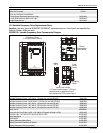
10.5.5 Variable Frequency Drive (VFD)
To replace the Variable Frequency Drive, turn off all
power to the drive assembly at the breaker or discon-
nect switch. Turn off 120 V power to the relay board
inside the ROBERTS GORDON
®
ULTRAVAC™ Con-
troller. Turn off the 24 V power switch on the relay
board.
Mark all wires connected to the VFD, noting the ter-
minals that they are secured to. Remove all wires
from the VFD terminals.
Remove the VFD from its mounting plate by remov-
ing the four securing screws.
Verify that the input voltage noted on the rating plate
of the VFD matches the input voltage of the old VFD.
Secure the new VFD to the mounting plate with the
four screws. Return all wires to the correct VFD ter-
minals. If possible, it may be easier to partially re-
wire the new VFD before mounting it to the mounting
plate.
Close the door and return power to the VFD. Return
120 V power to the relay board. Turn on the 24 V
power switch on the relay board. Press the reset but-
ton on the control board and close the doors.
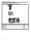
10.5.6 Variable Frequency Drive 25 A or 10 A Fuse
To replace a fuse, turn off inpu
t power to the variable
frequency drive assembly at the breaker or
disconnect switch.
Turn off 120 V power to the relay board inside the
ROBERTS GORDON
®
ULTRAVAC™ Controller. Turn
off the 24 V power switch on the relay board.
Inside the VFD assembly, open the fuse holder by
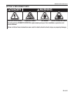
DANGER
Electrical Shock Hazard
Disconnect electric before service.
Controller must be properly grounded to an
electrical source.
Failure to follow these instructions can
result in death or electrical shock.